Heat pump system for vehicle

Active Publication Date: 2017-07-06
HANON SYST
View PDF9 Cites 6 Cited by
  • Summary
  • Abstract
  • Description
  • Claims
  • Application Information

AI Technical Summary

Benefits of technology

The heat pump system for vehicles described in this patent utilizes two blowers and an intake duct to efficiently supply indoor and outdoor air to the blowers. This maximizes space efficiency and reduces the size and manufacturing costs of the system. Additionally, the system includes a bypass door that improves heating performance by increasing the air volume and temperature induced into the evaporator. The arrangement of the evaporator and condenser allows for vertical placement, further increasing space efficiency and reducing the size and manufacturing costs of the system.

Problems solved by technology

In other words, because two intake ducts are respectively mounted on the two blowers 20, the heat pump system occupies a large installation space and the size and manufacturing costs of the heat pump system are increased.

Method used


Image

  • Heat pump system for vehicle
  • Heat pump system for vehicle
  • Heat pump system for vehicle

Examples


Embodiment Construction

[0033]Reference will be now made in detail to the preferred embodiment of the present invention with reference to the attached drawings.

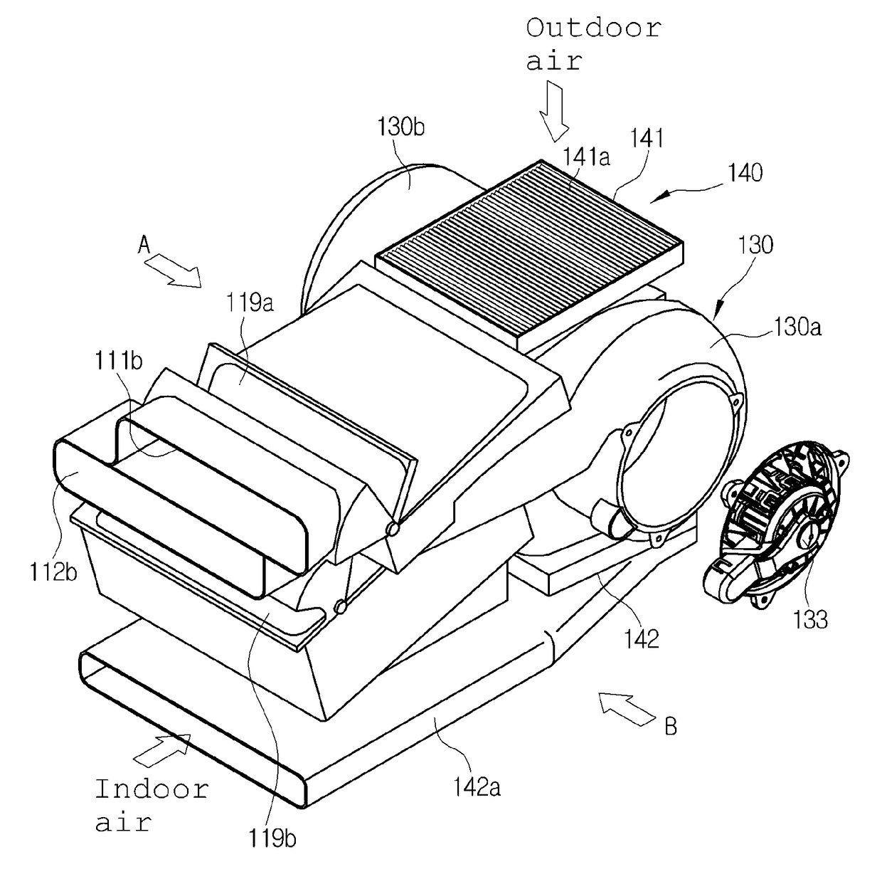
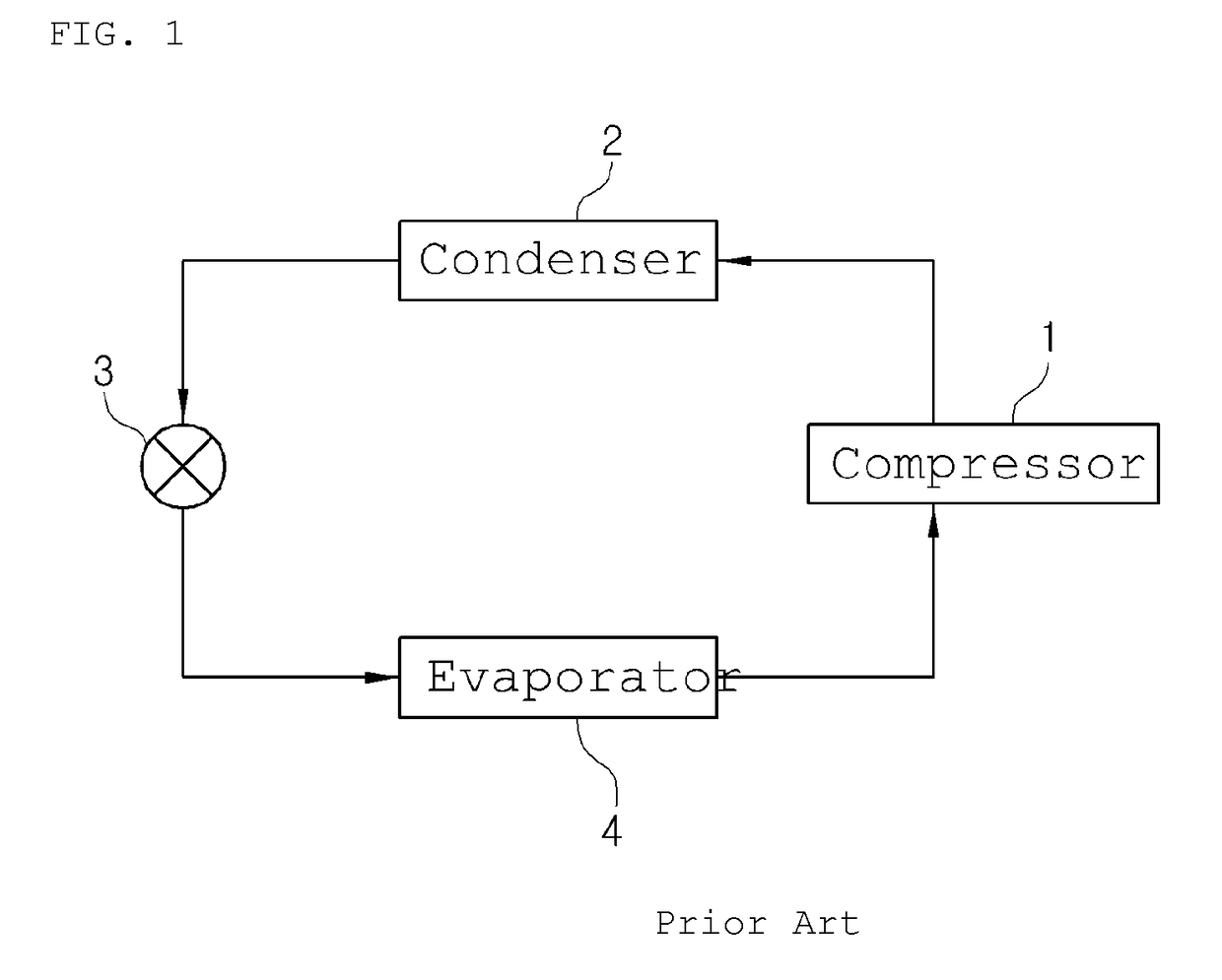
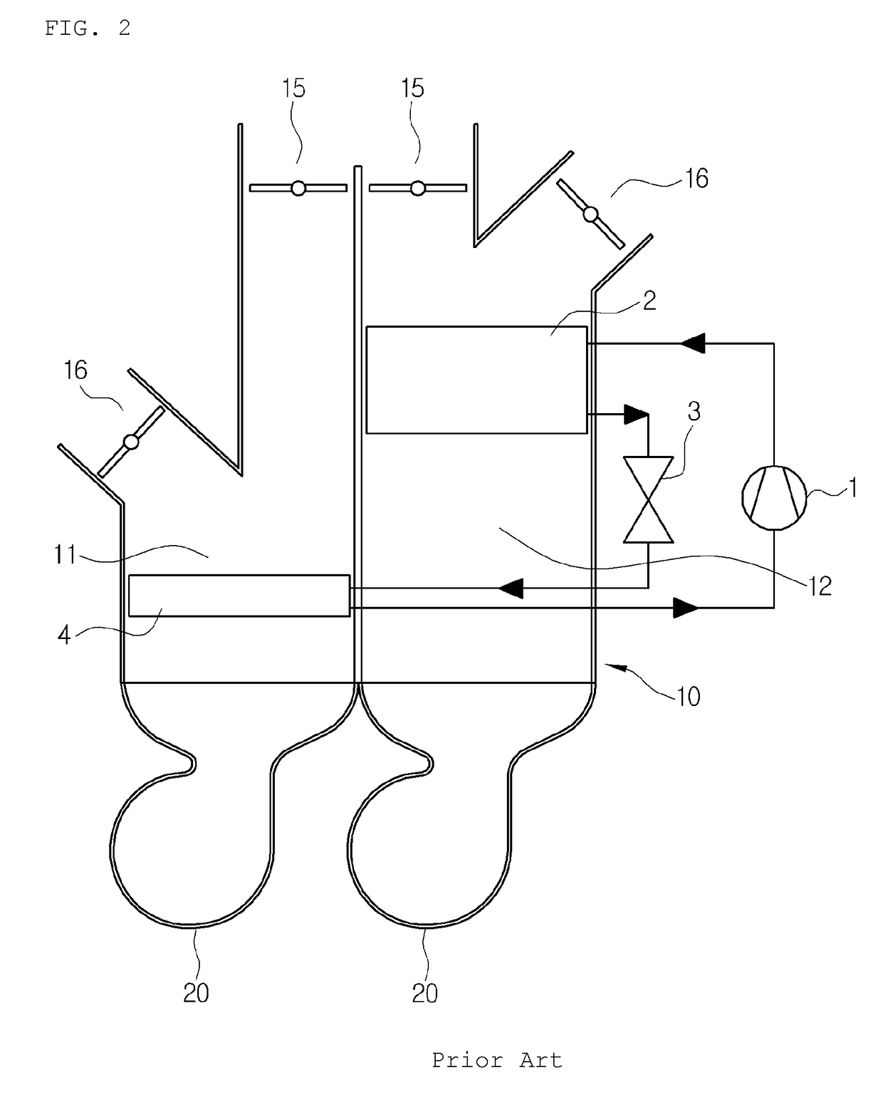
[0034]As shown in the drawings, a heat pump system for a vehicle according to the present invention includes a compressor 101, a condenser 102, expansion means (not shown) and an evaporator 104 which are connected with one another through a refrigerant circulation line (P) so as to carry out cooling through the evaporator 104 and carry out heating through the condenser 102.

[0035]First, the compressor 100 inhales and compresses gas-phase refrigerant of low-temperature and low-pressure discharged from the evaporator 104 while operating by receiving a driving force from a power supply, such as an engine or a motor, and then, discharges the refrigerant in a gas phase of high-temperature and high-pressure.

[0036]The condenser 102 exchanges heat between the gas-phase refrigerant of high-temperature and high-pressure, which is discharged from the compressor...


PUM


Abstract

Disclosed herein is a heat pump system for a vehicle which includes an evaporator mounted on a cold air passageway inside an air-conditioning case, a condenser mounted on a warm air passageway, a first blower mounted at an inlet side of the cold air passageway of the air-conditioning case, a second blower mounted at an inlet side of the warm air passageway and an intake duct mounted between the first blower and the second blower to supply indoor air and outdoor air to the first blower and the second blower respectively, thereby maximizing space efficiency because using just one intake duct for the two blowers, and reducing the size and manufacturing costs of the heat pump system.

Description

TECHNICAL FIELD[0001]The present invention relates to a heat pump system for a vehicle, and more particularly, to a heat pump system for a vehicle which includes an evaporator mounted on a cold air passageway inside an air-conditioning case, a condenser mounted on a warm air passageway, a first blower mounted at an inlet side of the cold air passageway of the air-conditioning case, a second blower mounted at an inlet side of the warm air passageway and an intake duct mounted between the first blower and the second blower to supply indoor air and outdoor air to the first blower and the second blower respectively.BACKGROUND ART[0002]In general, as shown in FIG. 1, an air conditioner system for a vehicle has a refrigeration cycle that includes: a compressor 1 for compressing and discharging refrigerant; a condenser 2 for condensing the refrigerant of high pressure discharged from the compressor 1; an expansion valve 3 for throttling the refrigerant condensed and liquefied in the conden...

Claims


Application Information

Patent Timeline
IPC IPC(8): B60H1/00B60H3/06
CPCB60H3/06B60H1/00057B60H1/00899B60H1/00321B60H1/00457B60H1/00521F25B30/02B60H2001/00099B60H2001/00107B60H2001/00178B60H1/00471
Inventor LEE, SUNG JEPARK, TAE YONGSEO, EUN YOUNGAHN, YONG NAMLEE, SE MINHAN, SEONG SEOK
Owner HANON SYST
Why Eureka
Try Eureka