
Magnetic Coupling Device of a Limb Prosthesis

Active Publication Date: 2013-10-31
NERO AG +1
View PDF7 Cites 9 Cited by
  • Summary
  • Abstract
  • Description
  • Claims
  • Application Information

AI Technical Summary

Benefits of technology

The present invention is a coupling device for a limb prosthesis that is embedded within the residual limb socket to solve the problems of donning and doffing. The device is simple and user-friendly, making it easy for amputees to use. The technical effects of this invention are to improve the comfort and convenience of wearing a limb prosthesis.

Problems solved by technology

The existing systems, however, suffer from a number of shortcomings.
One is that the system may result in distal tissue stretching, and pistoning of the prosthesis.
This can cause permanent elongation of distal tissue and augment pistoning.
Furthermore, the use of the systems may lead to pain, particularly along the tibial crest and cut end of the tibia among transtibial amputees and cut end of the femur among transfemoral amputees.
Some patients may experience problem when aligning pin with the plunger pin hole or disengaging pin from the pin lock, particularly to the patients with poor flexibility, strength, and / or manual dexterity, thus causing difficulty and dissatisfaction among the amputees, and raise the problem of aligning and adjusting the liner to the socket.
Also, the complex design of the suspension system renders high cost and time consumption, as well as system failure or improper function due to the accumulation of dust, dirt and other debris within the system.
In addition, the donning and doffing problems may arise if the configuration of the systems is complicated.

Method used


Image

  • Magnetic Coupling Device of a Limb Prosthesis
  • Magnetic Coupling Device of a Limb Prosthesis
  • Magnetic Coupling Device of a Limb Prosthesis

Examples


Embodiment Construction

[0023]As required, detailed embodiments of the present invention are disclosed herein; however, it is to be understood that the disclosed embodiments are merely exemplary of the invention, which may be embodied in various forms. Therefore, specific structural and functional details disclosed herein are not to be interpreted as limiting but merely as a basis for claims. It should be understood that the drawings and detailed description thereto are not intended to limit the invention to the particular form disclosed, but on the contrary, the invention is to cover all modification, equivalents and alternatives falling within the scope of the present invention as defined by the appended claims. As used throughout this application, the word “may” is used in a permissive sense (i.e., meaning having the potential to), rather than the mandatory sense (i.e., meaning must). Similarly, the words “include,”“including,” and “includes” mean including, but not limited to. Further, the words “a” or...


PUM


Abstract

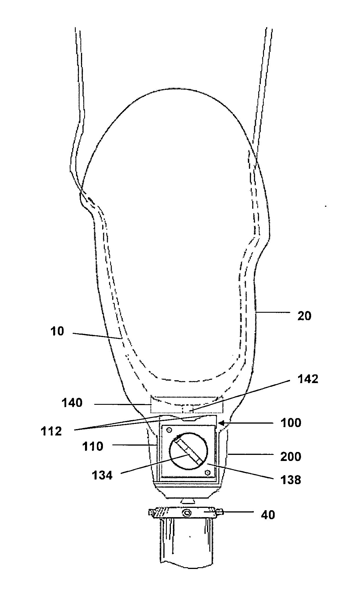
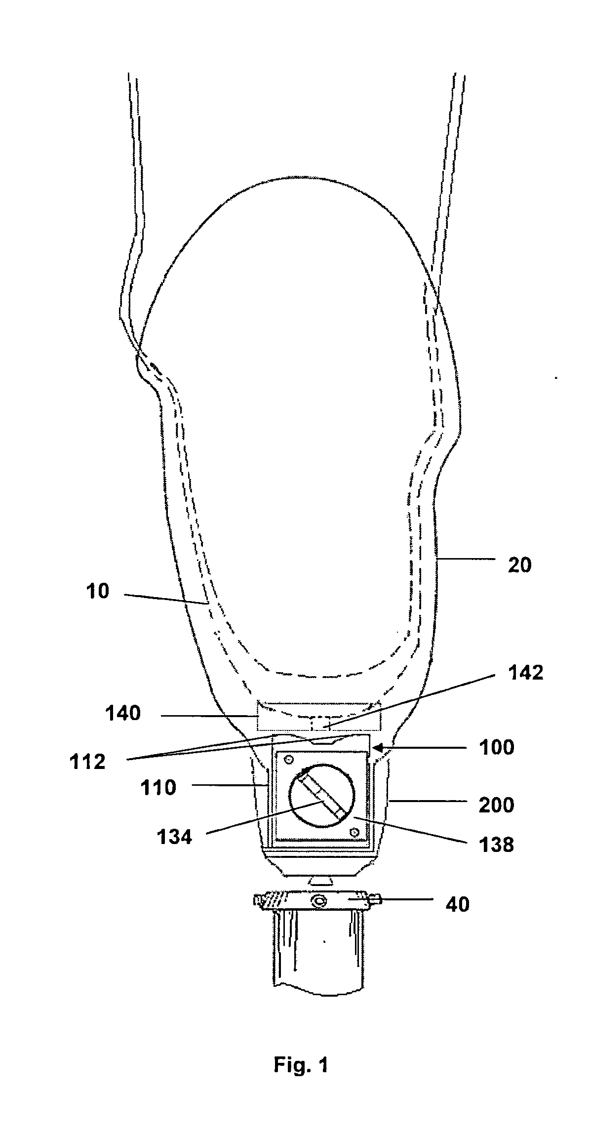
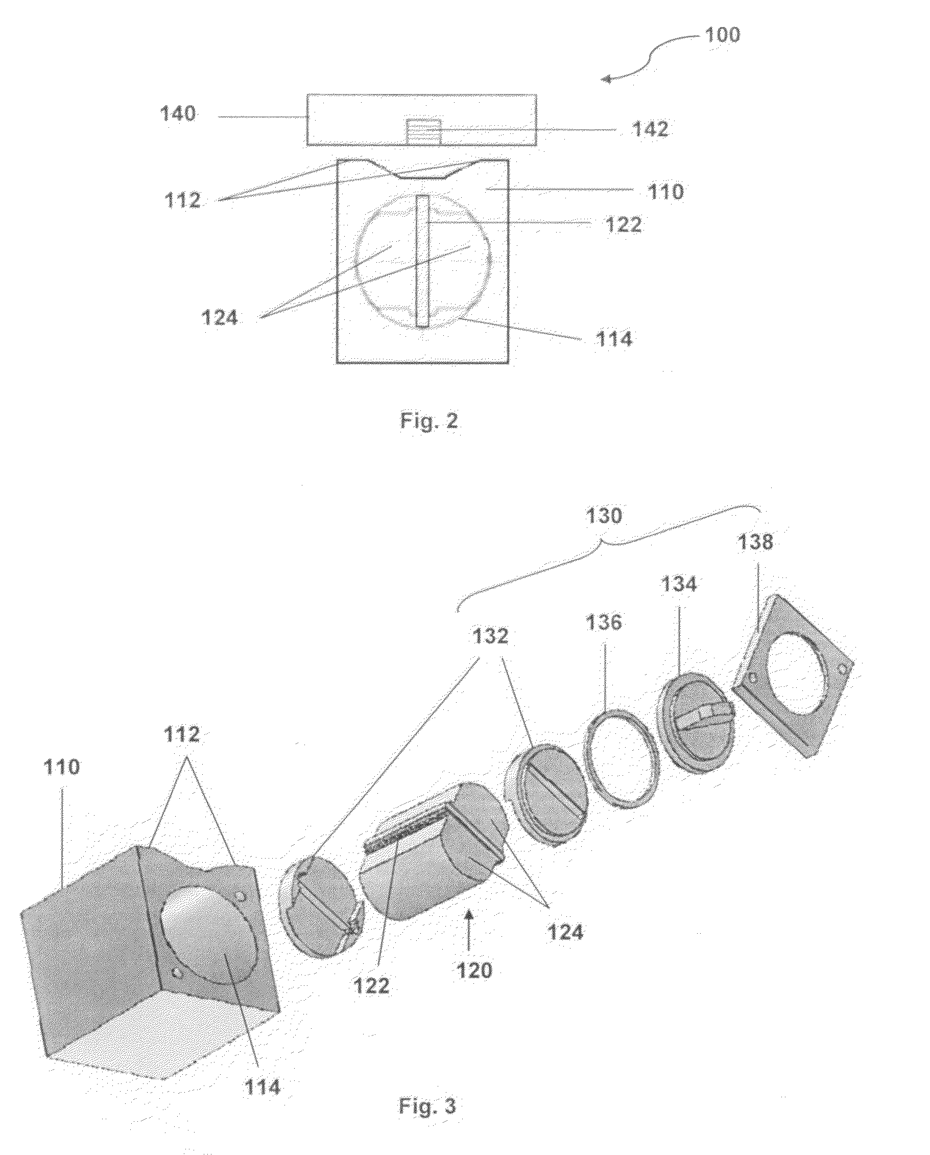
The present invention relates to a coupling device (100) for connecting a residual limb liner (10) to a residual limb socket (20) of a limb prosthesis, characterised by: a magnet assembly (120) comprising a permanent magnet (122) sandwiched by a pair of iron bars (124) for creating a magnetic field; a housing (110) comprising a protrusion (112) for intensifying magnetic field and a cavity (114) for receiving the magnet assembly (120), wherein said housing (110) is embedded at a distal end of the residual limb socket (20); a controlling means (130) coupled to the housing (110) and the magnet assembly (120) for controlling the magnetic field by rotating the magnet assembly (120); and a mounting plate (140) coupled to the residual limb liner (10); wherein the mounting plate (140) is attracted to the protrusion (112) of the housing (110) when the permanent magnet (122) is vertically aligned, thereby attaching the residual limb liner (10) to the residual limb socket (20); and wherein the mounting plate (140) is repelled from the protrusion (112) of the housing (110) when the permanent magnet (122) is horizontally aligned, thereby detaching the residual limb liner (10) from the residual limb socket (20).

Description

BACKGROUND OF THE INVENTION[0001]1. Field of the Invention[0002]This invention relates to a coupling device for a limb prosthesis, and more particularly to a magnetic coupling device for connecting a residual limb liner to a residual limb socket of a limb prosthesis, which is applicable for lower limb prosthesis as well as for upper limb prosthesis.[0003]2. Description of Related Arts[0004]Lower limb prosthetics are artificial devices designed to replace the function or appearance of all or a part of the missing lower limb. In contrast, lower limb orthotic devices are designed to support, supplement, or augment the function of an existing lower limb.[0005]All types of lower limb prosthesis include a foot and socket. The socket is part of the prosthesis that connects to the stump. The stump is the end of the lower limb. A pylon is a tube connecting the socket to the foot. A pylon may be used to transfer body weight from the socket to the foot. A suspension system or a coupling system...

Claims


Application Information

Patent Timeline
IPC IPC(8): A61F2/78
CPCA61F2/7812A61F2/78A61F2/80
Inventor ABU OSMAN, MADYA NOOR AZUANESHRAGHI, AREZOO
Owner NERO AG
Learn More