
Full speed lane sensing with a surrounding view system

Active Publication Date: 2013-11-07
GM GLOBAL TECH OPERATIONS LLC
View PDF26 Cites 44 Cited by
  • Summary
  • Abstract
  • Description
  • Claims
  • Application Information

AI Technical Summary

Benefits of technology

The present invention provides a system and method for sensing the lanes on a vehicle by detecting roadway markers in a top-down view image captured by a surround view camera system. The system can detect the boundaries of the lanes and align them from image to image. This allows the system to accurately identify the location of the boundary lines on the roadway, even if they are not perfectly aligned. The technical effect of the invention is improved accuracy and reliability in identifying the vehicle's lanes and improving safety on the road.

Problems solved by technology

However, there are various situations where a single camera may not be able to detect the lane-markers, including a low sun angle, non-visible lane markings as a result of close proximity vehicles, such as in congested traffic situations, camera failure, etc.
For example, when a leading-vehicle is too close to the subject vehicle, due to traffic congestion or other traffic situations, the camera may not detect the lane-markers because the lane-markers are hidden by the leading-vehicle, and thus, lane-marker detection of the lane will fail.

Method used


Image

  • Full speed lane sensing with a surrounding view system
  • Full speed lane sensing with a surrounding view system
  • Full speed lane sensing with a surrounding view system

Examples


Embodiment Construction

[0021]The following discussion of the embodiments of the invention directed to a system and method for providing vehicle lane sensing by detecting lane-markers using a surround view camera system is merely exemplary in nature, and is in no way intended to limit the invention or its applications or uses.

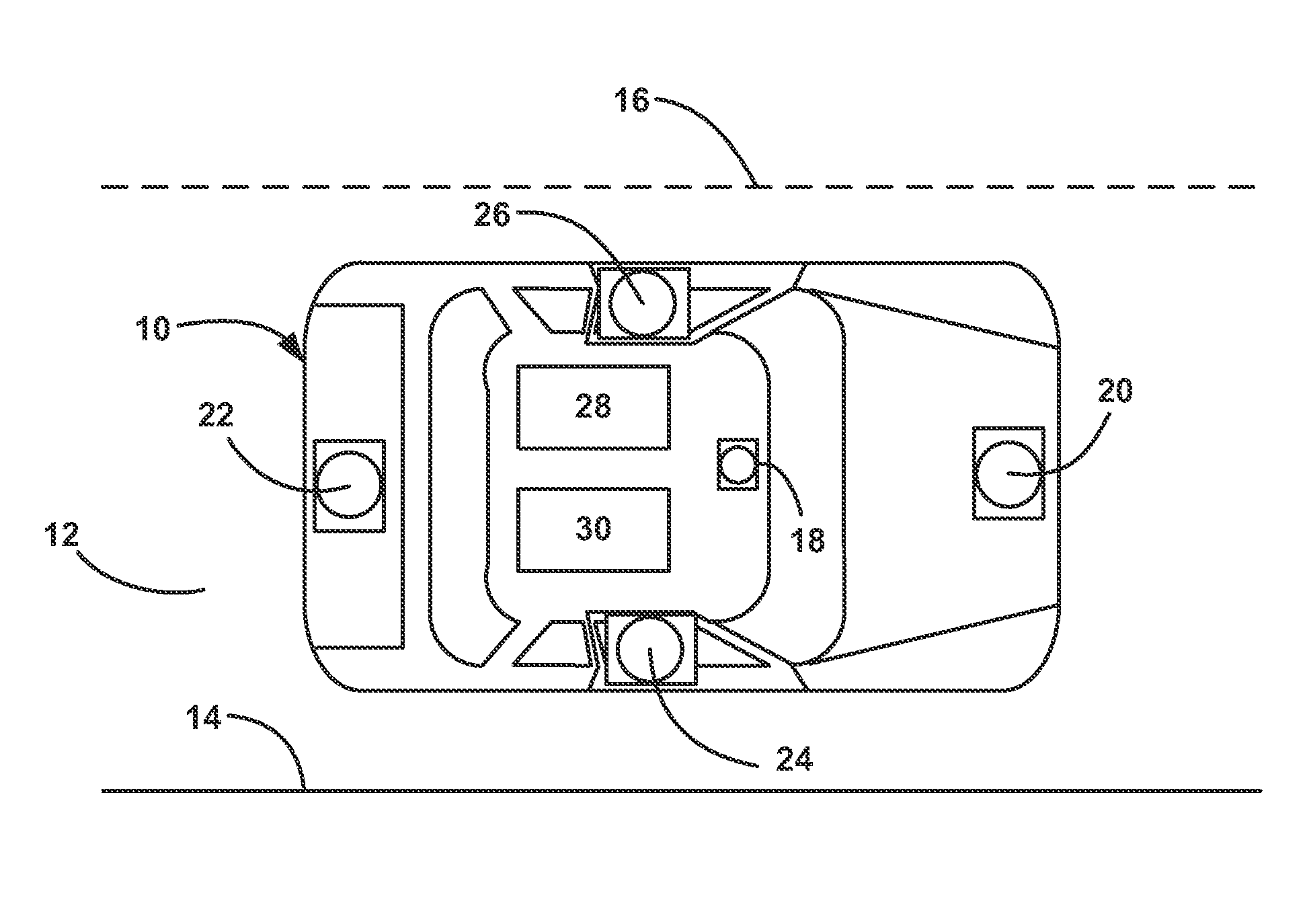
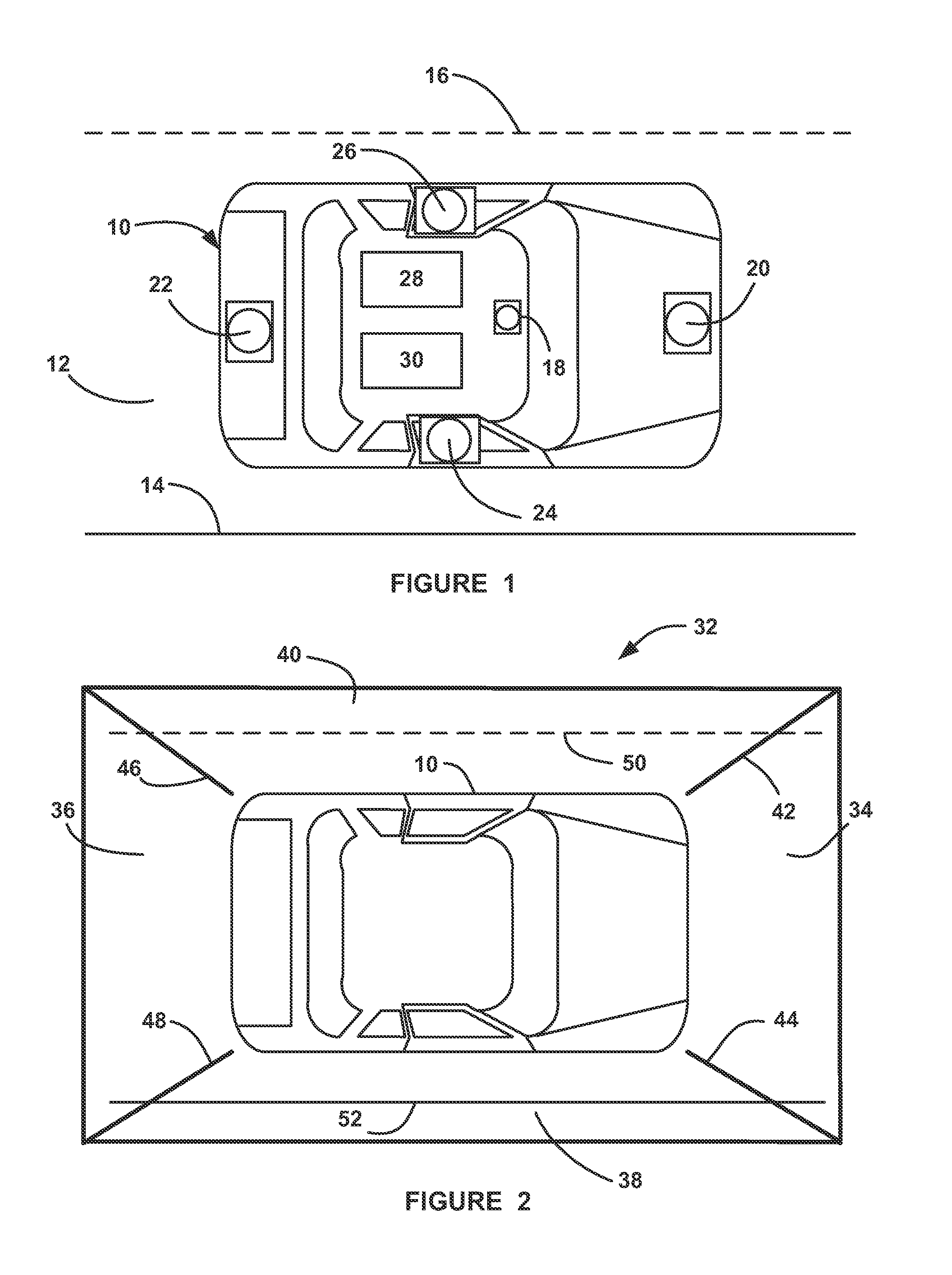
[0022]FIG. 1 is an illustration of a vehicle 10 traveling along a roadway lane 12 that is defined by lane-markers painted or otherwise affixed on the roadway lane 12 including a solid outside lane boundary line 14 and a dashed lane center line 16. The vehicle 10 includes a camera 18 within the vehicle 10, such as behind the rear-view mirror (not shown), for reasons that will become apparent from the discussion below. The vehicle 10 also includes a surround view camera system having a front-view camera 20, a rear-view camera 22, a right-side view camera 24 and a left-side view camera 26. The cameras 20-26 can be any camera suitable for the purposes described herein, many of which are k...


PUM


Abstract

A system and method for providing lane sensing on a vehicle by detecting roadway lane-markers, where the system employs a surround view camera system providing a top-down view image around the vehicle. The method includes detecting left-side and right-side lane boundary lines in the top-down view image, and then determining whether the lane boundary lines in the image are aligned from one image frame to a next image frame and are aligned from image to image in the top-down view image. If the boundary lines are not aligned, then calibration of one or more of the cameras is performed, and if the lines are aligned, then a model fitting process is used to specifically identify the location of the boundary lines on the roadway.

Description

CROSS-REFERENCE TO RELATED APPLICATIONS[0001]This application claims the benefit of the priority date of U.S. Provisional Patent Application Ser. No. 61 / 641,479, titled, Full Speed Lane Sensing With A Surrounding View System, filed May 2, 2012.BACKGROUND OF THE INVENTION[0002]1. Field of the Invention[0003]This invention relates generally to a system and method for providing roadway lane sensing for a vehicle traveling in the lane and, more particularly, to a system and method for providing roadway lane sensing on a vehicle traveling within the lane, where the lane sensing system employs an algorithm that uses a top-down view image generated from four cameras that provide images all the way around the vehicle.[0004]2. Discussion of the Related Art[0005]Modern vehicles are becoming more autonomous, i.e., vehicles are able to provide driving control with less driver intervention. Cruise control systems have been on vehicles for a number of years where the vehicle operator can set a pa...

Claims


Application Information

Patent Timeline
IPC IPC(8): H04N7/18
CPCH04N7/181G06V20/588
Inventor ZHANG, WENDELITKOUHI, BAKHTIAR BRIANLYBECKER, KENT S.
Owner GM GLOBAL TECH OPERATIONS LLC
Learn More