Supercharge Your Innovation With Domain-Expert AI Agents!

System for characterizing tire uniformity machines and methods of using the characterizations

a tire uniformity machine and tire technology, applied in the direction of vehicle testing, structural/machine measurement, ways, etc., can solve the problems of undesirable exciting force in the tire, difficulty in mass production of ideal tires, and variety of vehicle oscillations and noises

Active Publication Date: 2013-11-14
AKRON SPECIAL MACHINERY
View PDF12 Cites 6 Cited by
  • Summary
  • Abstract
  • Description
  • Claims
  • Application Information

AI Technical Summary

Benefits of technology

This patent describes a system for characterizing tire uniformity machines and methods of using the characterizations. The system includes a tire uniformity machine with a load wheel for applying a force to the tire and a spindle alignment assembly to ensure accurate results. A control tire with known characteristics is used to align the spindles, and the load wheel force is detected and correlated with the angular position of the load wheel to create a characteristic waveform of the spindles. The system allows for improved accuracy and consistency in tire testing.

Problems solved by technology

However, the usual tire construction and manufacturing process make it difficult to mass produce such an ideal tire.
As a result, an undesirable exciting force is produced in the tire while the vehicle is running.
The oscillations produced by this exciting force are transmitted to the vehicle chassis and cause a variety of vehicle oscillations and noises including shaking, fluttering, and sounds of the tire vibrations being transmitted inside the vehicle.
As skilled artisans will appreciate, filtering the test results undesirably adds time to the test procedure.
Filtering also raises concerns that the filters may be set to exclude tires that are acceptable and, more problematically, tires that are not acceptable may be passed to allowance.
One approach is to generate characterization plots of components of the tire uniformity machine that adversely affect the true uniformity of the tire under test.
It is believed that each rotating drum that contacts the tire's surface and each upper and lower spindle and chuck assembly that engages the tire's bead has a unique force characteristic that contributes errors into the uniformity measurements detected by the machine.
It is also believed that prior attempts to adequately characterize the load wheel and the spindle characterization are deficient.
In particular, prior methods did not adequately consider differences between the angular alignment or rotational position of the upper and lower spindle and chuck assemblies.
As a result, different angular alignments of the spindle and chuck assemblies result in force contributions to a tire uniformity measurement that are not adequately filtered or that distort the filtered measurements in a way that does not accurately represent a tire uniformity measurement.

Method used


Image

  • System for characterizing tire uniformity machines and methods of using the characterizations
  • System for characterizing tire uniformity machines and methods of using the characterizations
  • System for characterizing tire uniformity machines and methods of using the characterizations

Examples


Embodiment Construction

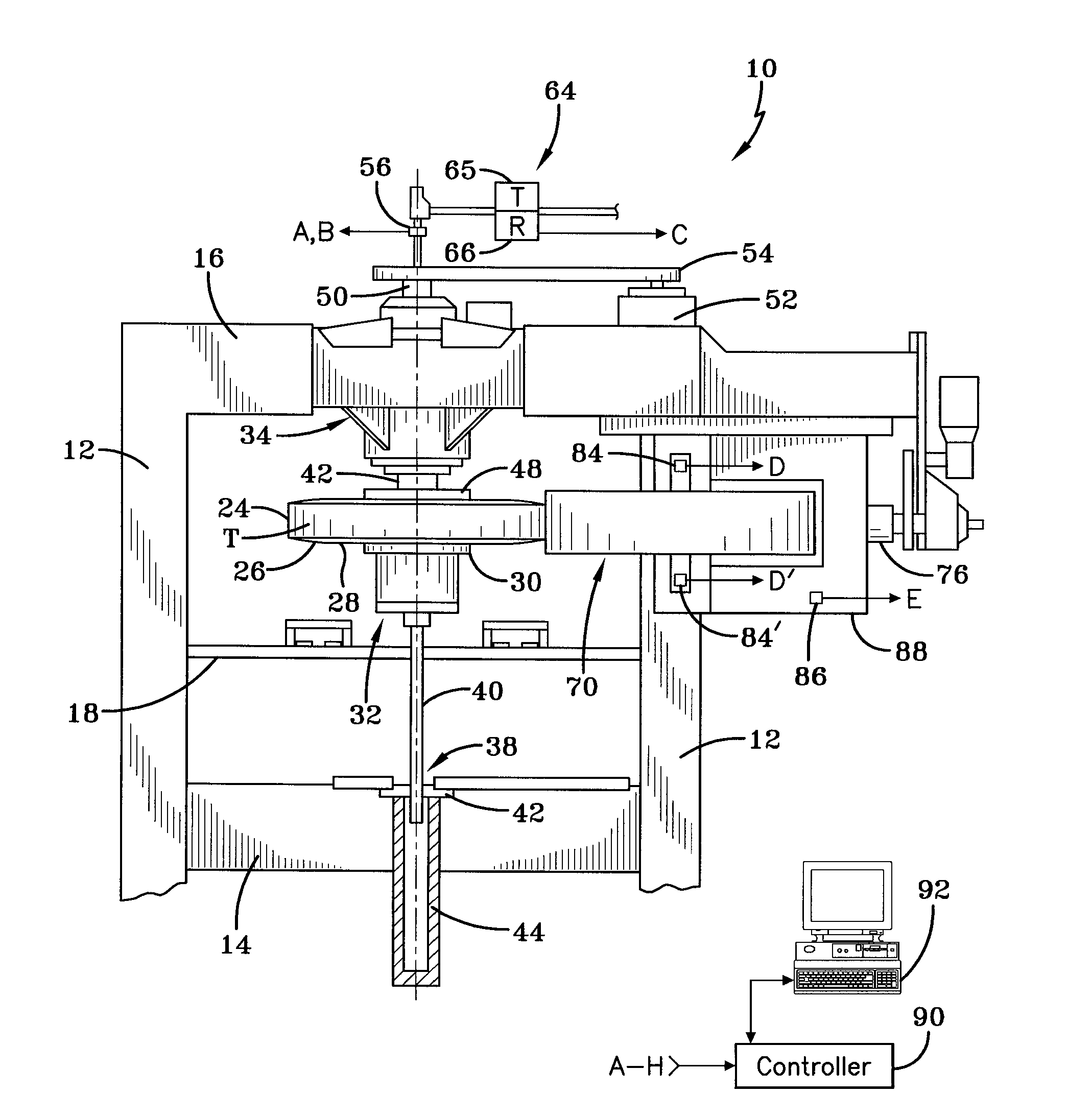
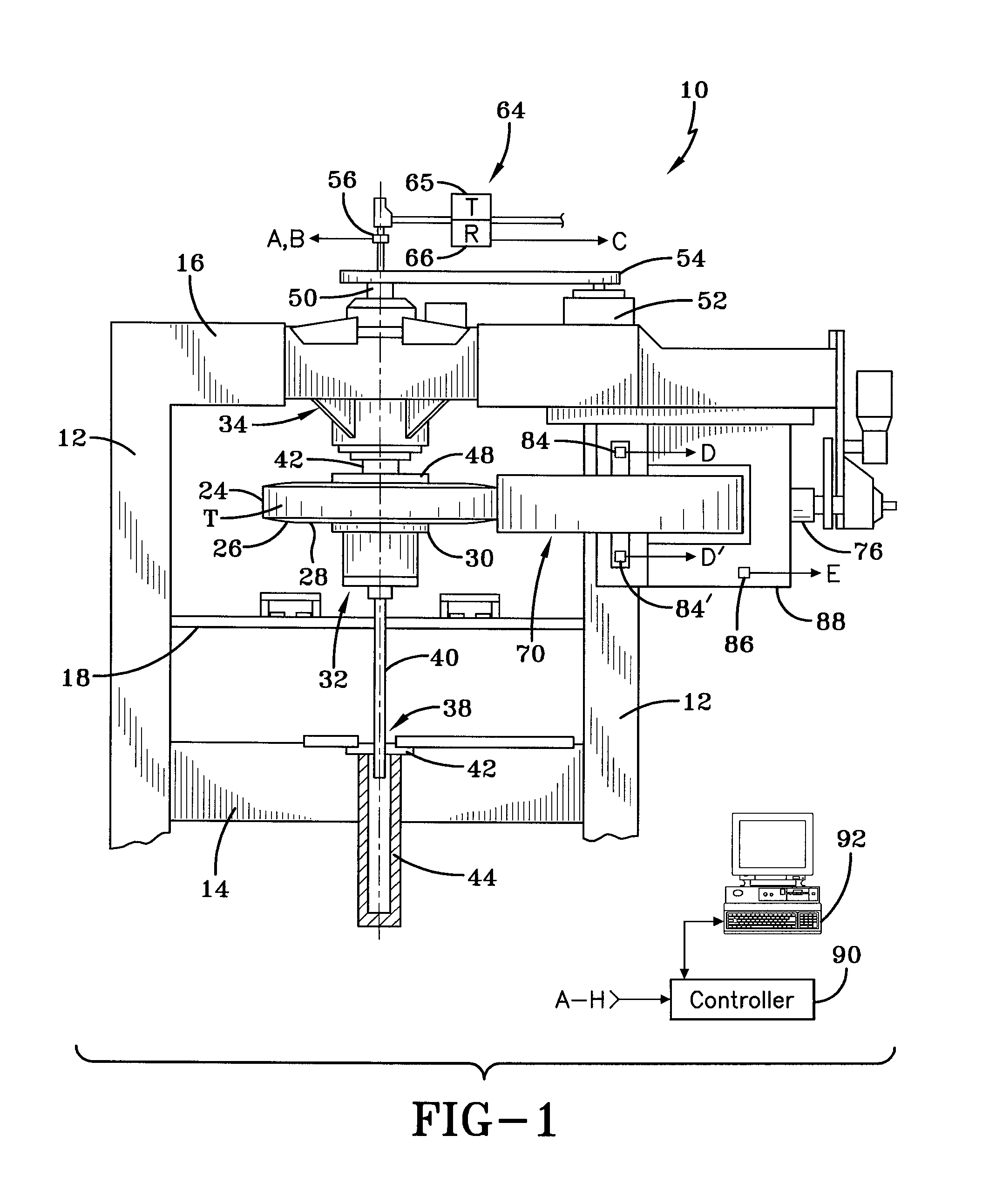
[0028]Referring now to the drawings and in particular to FIG. 1, it can be seen that a tire uniformity machine is designated generally by the numeral 10. The machine includes side frame members 12 which are connected at respective ends by a horizontal bottom frame member 14 and a horizontal top frame member 16. The side frame members 12 and frame members 14 and 16 form a box-like structure within which a tire, designated generally by the capital letter T is received, tested and discharged.

[0029]A conveyor 18 is configured with rollers which have openings therebetween upon which the tire T is delivered to the machine 10. Each tire T includes a tread 24 adjacent substantially parallel sidewalls 26 which have beads 28 forming an inner diameter of the tire.

[0030]The machine 10 includes an apparatus for receiving and rotating the tire and, in particular, a lower spindle and chuck assembly 32 and an upper spindle and chuck assembly 34. Both the lower and upper spindle and chuck assemblies...


PUM


Abstract

A tire uniformity machine includes an apparatus for receiving and rotating a tire. The apparatus includes opposed spindles for receiving, inflating and rotating a tire, and a load wheel applied to the rotating tire to obtain tire test results. A spindle alignment assembly is associated with the opposed spindles to align the spindles with one another each time a tire is received. At least one characterizing device is associated with components of the apparatus to characterize forces of the opposed spindles and the characterized forces are used in adjusting tire test results.

Description

CROSS-REFERENCE TO RELATED APPLICATIONS[0001]This application is a Continuation-In-Part application of U.S. patent application Ser. No. 13 / 370,541 filed Feb. 10, 2012, which is incorporated herein by reference.TECHNICAL FIELD[0002]The present invention relates generally to tire testing equipment. In particular, the present invention relates to characterizing components of a tire uniformity machine. Specifically, the present invention relates to using characterizations of the tire uniformity machine for evaluating tires during normal testing procedures.BACKGROUND ART[0003]Ideally, a tire is desirable to be a perfect circle, and interior stiffness, dimensions and weight distribution and other features thereof should be uniform around the circumference of the tire. However, the usual tire construction and manufacturing process make it difficult to mass produce such an ideal tire. That is, a certain amount of nonuniformity in the stiffness, dimensions and weight distribution and other f...

Claims


Application Information

Patent Timeline
IPC IPC(8): G01M17/02
CPCG01M17/022G01M17/021
Inventor STANOSZEK, BYRON R.POLING, JR., DAVID L.MITCHELL, BRIANHAINES, MICHAELHASBACH, ALEXANDER
Owner AKRON SPECIAL MACHINERY
Features
  • R&D
  • Intellectual Property
  • Life Sciences
  • Materials
  • Tech Scout
  • Unparalleled Data Quality
  • Higher Quality Content
  • 60% Fewer Hallucinations
Learn More