Light deflector
a technology of optical deflectors and light beams, applied in the field of optical deflectors, can solve problems such as increasing rigidity, and achieve the effect of increasing torsional rigidity
- Summary
- Abstract
- Description
- Claims
- Application Information
AI Technical Summary
Benefits of technology
Problems solved by technology
Method used
Image
Examples
first embodiment
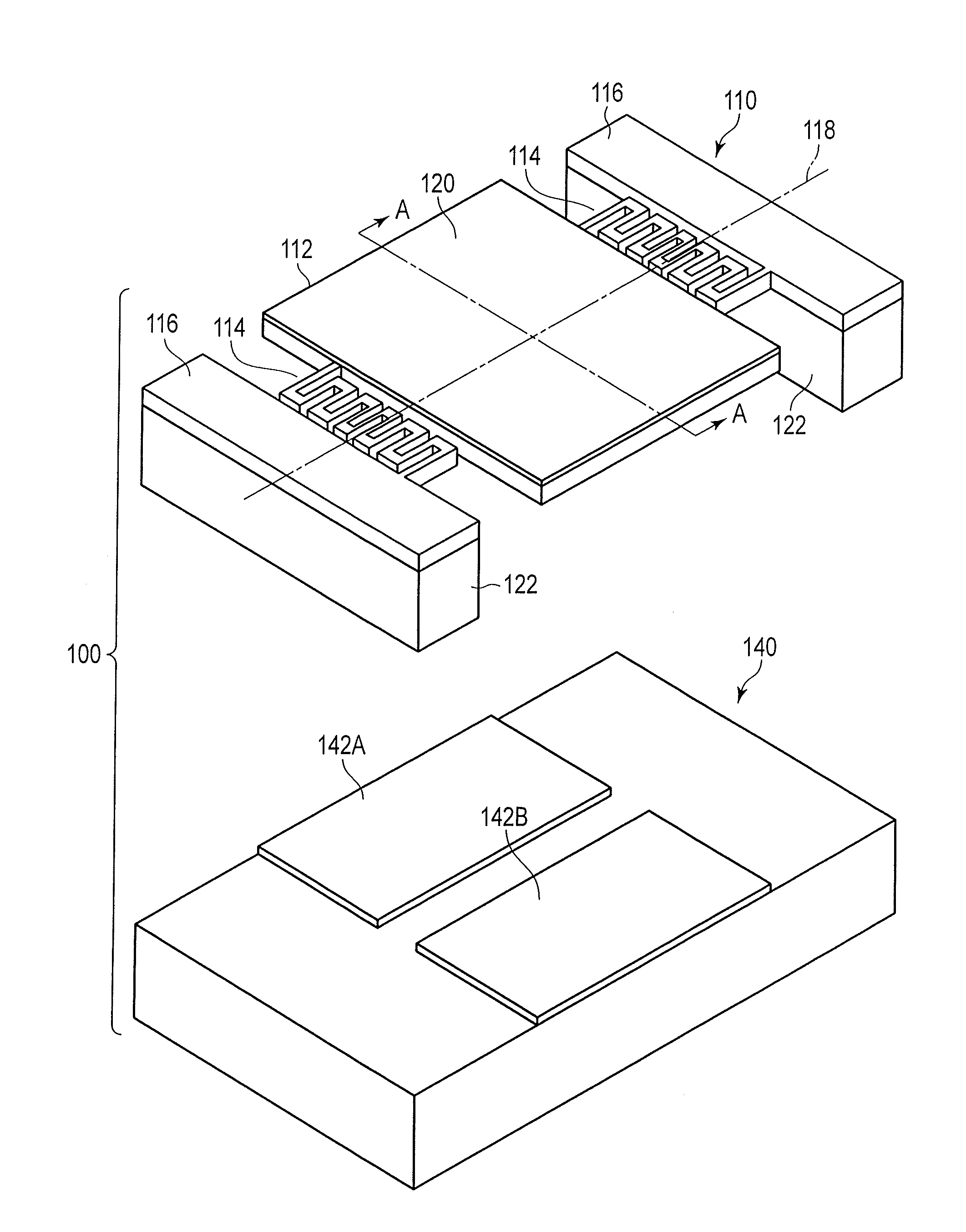
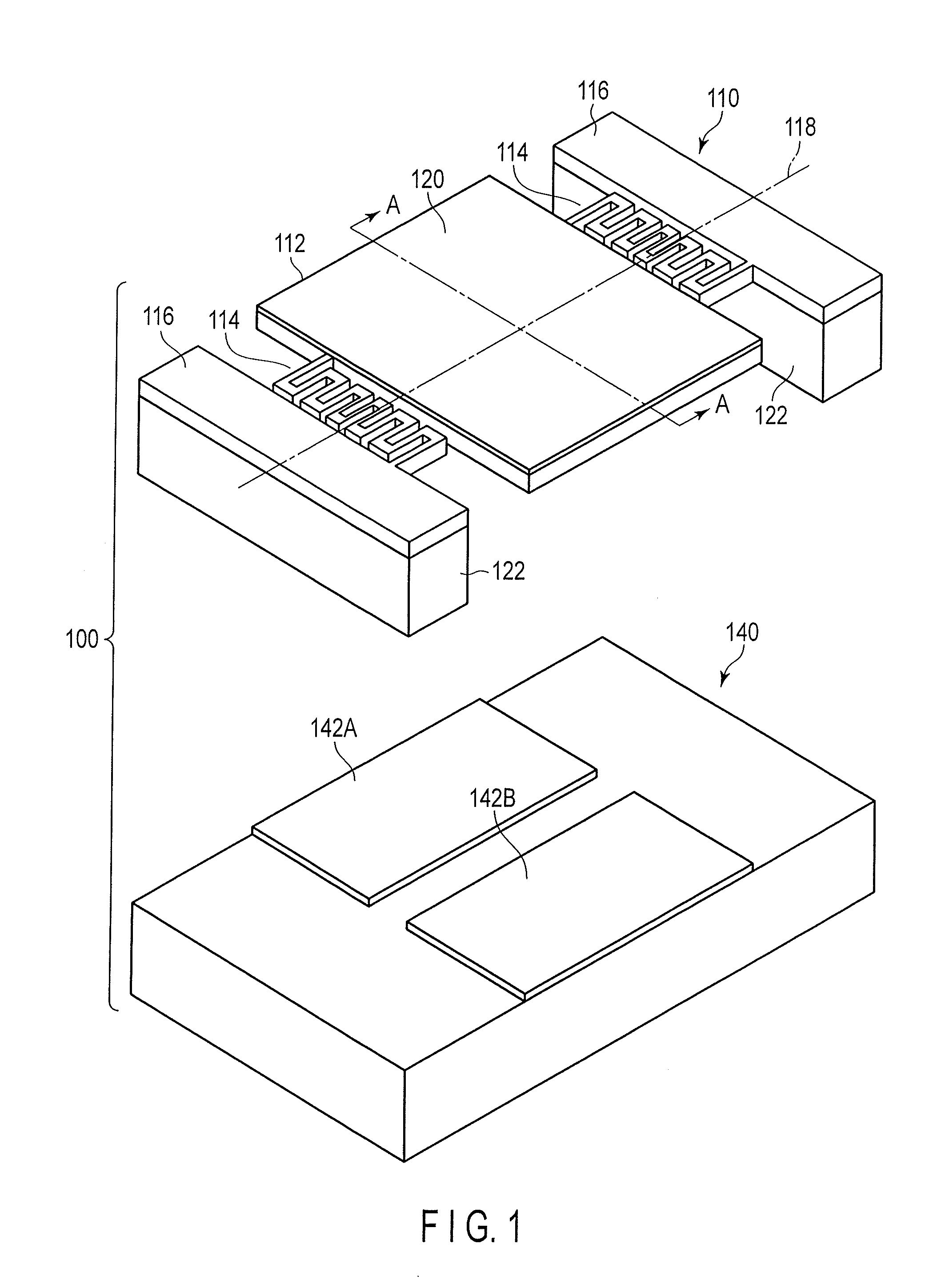
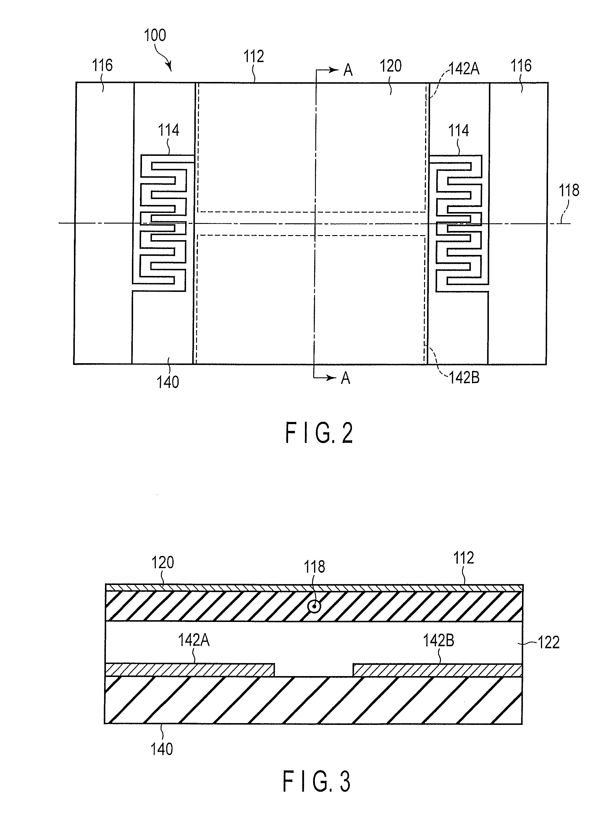
[0035]A configuration of an optical deflector according to a first embodiment will be first described with reference to FIGS. 1 to 4. FIG. 1 is a disassembled perspective view of an optical deflector according to the first embodiment. FIG. 2 is a plan view of the optical deflector shown in FIG. 1. FIG. 3 shows a joint cross section of the optical deflector taken along a line A-A shown in FIG. 1. FIG. 4 is an enlarged perspective view of a combined torsion bar of the optical deflector shown in FIG. 1.
[0036]An optical deflector 100 comprises a mirror unit 110 and an electrode substrate 140.
[0037]The mirror unit 110 comprises a movable portion 112, a pair of combined torsion bars 114, and a pair of fixed portions 116. The movable portion 112 has a rectangular shape. The shape of the movable portion 112 is not limited to the rectangular shape, and any other arbitrary shape such as a circular shape or an elliptic shape may be adopted. The pair of fixed portions 116 are positioned on both...
second embodiment
[0166]A second embodiment will now be described with reference to FIG. 22. This second embodiment aims at another combined torsion bar that can be applied in place of the combined torsion bar according to the first embodiment. FIG. 22 is a plan view of one combined torsion bar according to the second embodiment.
[0167]As shown in FIG. 22, a combined torsion bar comprises an odd number of torsion bars 2TB1-2TB11 and a plurality of connecting bars 2CB1-2CB10. The torsion bars 2TB1-2TB11 extend to be parallel to each other. Each of the connecting bars 2CB1-2CB10 connects one ends of each adjacent two of the torsion bars 12B1-2TB11 to each other. That is, the connecting bar 2CBn (n is a natural number that is not greater than 10) connects one ends of the two torsion bars 2TBn, 2TBn+1 to each other. The other ends of the two torsion bars 2TB1, 2TB11 positioned on the outermost side, i.e., ends that are not connected to the connecting bars 2CB1, 2CB10 are connected to the movable portion 1...
third embodiment
[0175]A third embodiment will now be described with reference to FIG. 23. This third embodiment aims at another torsion bar that can be applied in place of the combined torsion bar according to the first embodiment. FIG. 23 is a plan view of one combined torsion bar according to the third embodiment.
[0176]As shown in FIG. 23, a combined torsion bar comprises an odd number of torsion bars 3TB1-3TB11 and a plurality of connecting bars 3CB1-3CB10. The torsion bars 3TB1-3TB11 extend to be parallel to each other. Each of the connecting bars 3CB1-3CB10 connects one ends of each adjacent two of the torsion bars 3TB1-3TB11 to each other. That is, the connecting bar 3CBn (n is a natural number that is not greater than 10) connects one ends of the two torsion bars 3TBn, 3TBn+1 to each other. The other ends of the two torsion bars 3TB1, 3TB11 positioned on the outermost side, i.e., ends that are not connected to the connecting bars 3CB1, 3CB10 are connected to the movable portion 112 and the f...
PUM
 Abstract
Description
Claims
Application Information
 - R&D
- Intellectual Property
- Life Sciences
- Materials
- Tech Scout
- Unparalleled Data Quality
- Higher Quality Content
- 60% Fewer Hallucinations
Browse by: Latest US Patents, China's latest patents, Technical Efficacy Thesaurus, Application Domain, Technology Topic, Popular Technical Reports.
© 2025 PatSnap. All rights reserved.Legal|Privacy policy|Modern Slavery Act Transparency Statement|Sitemap|About US| Contact US: help@patsnap.com


