Manufacturing method and golf club head

a golf club and manufacturing method technology, applied in the field of golf club heads, can solve the problems of deterioration of impact feel, and affecting the impact feel so as to improve the impact feel and the abrasion resistance of portions surrounding the scorelin

Active Publication Date: 2013-11-14
BRIDGESTONE SPORTS
View PDF3 Cites 192 Cited by
  • Summary
  • Abstract
  • Description
  • Claims
  • Application Information

AI Technical Summary

Benefits of technology

[0006]It is an object of the present invention to make it possible to improve both an impact feel and the abrasion resistance of portions surrounding scorelines.

Problems solved by technology

However, when a soft material is used, portions surrounding scorelines are likely to wear.
As portions surrounding scorelines wear more severely, the spin amount on a struck golf ball decreases.
If a golf club head is formed by a hard material, portions surrounding scorelines become harder to wear, but an impact feel deteriorates.

Method used


Image

  • Manufacturing method and golf club head
  • Manufacturing method and golf club head
  • Manufacturing method and golf club head

Examples


first embodiment

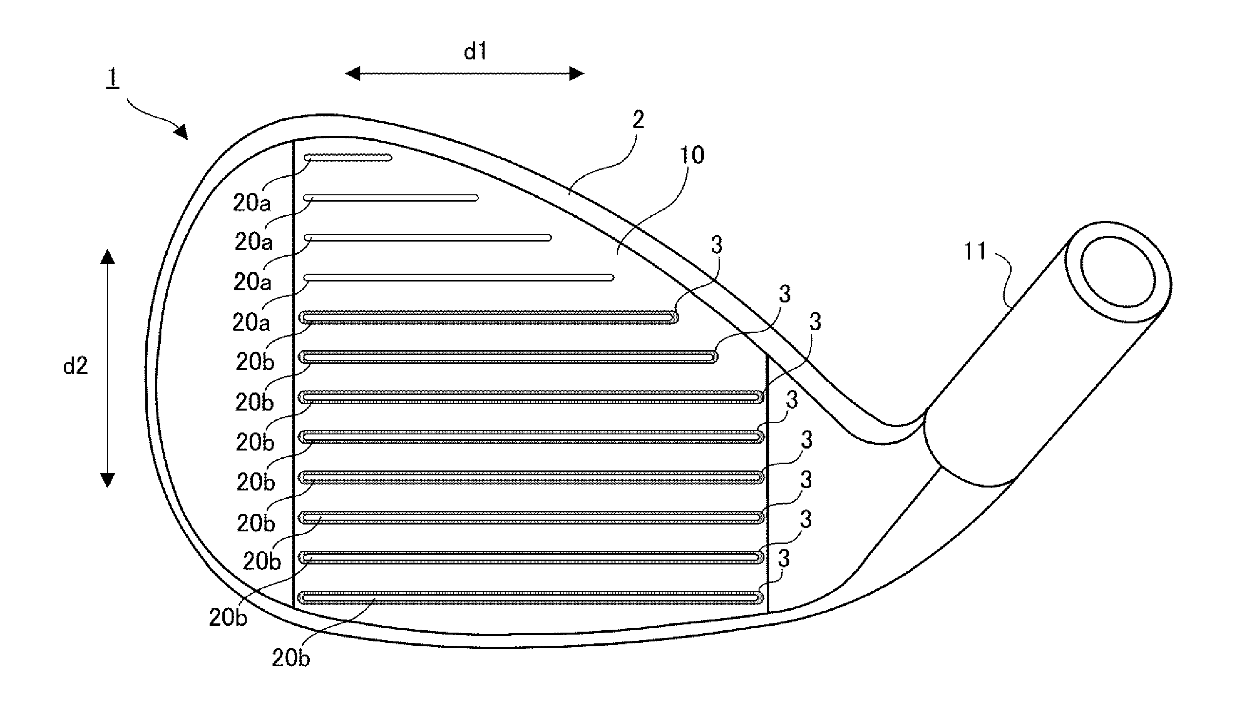
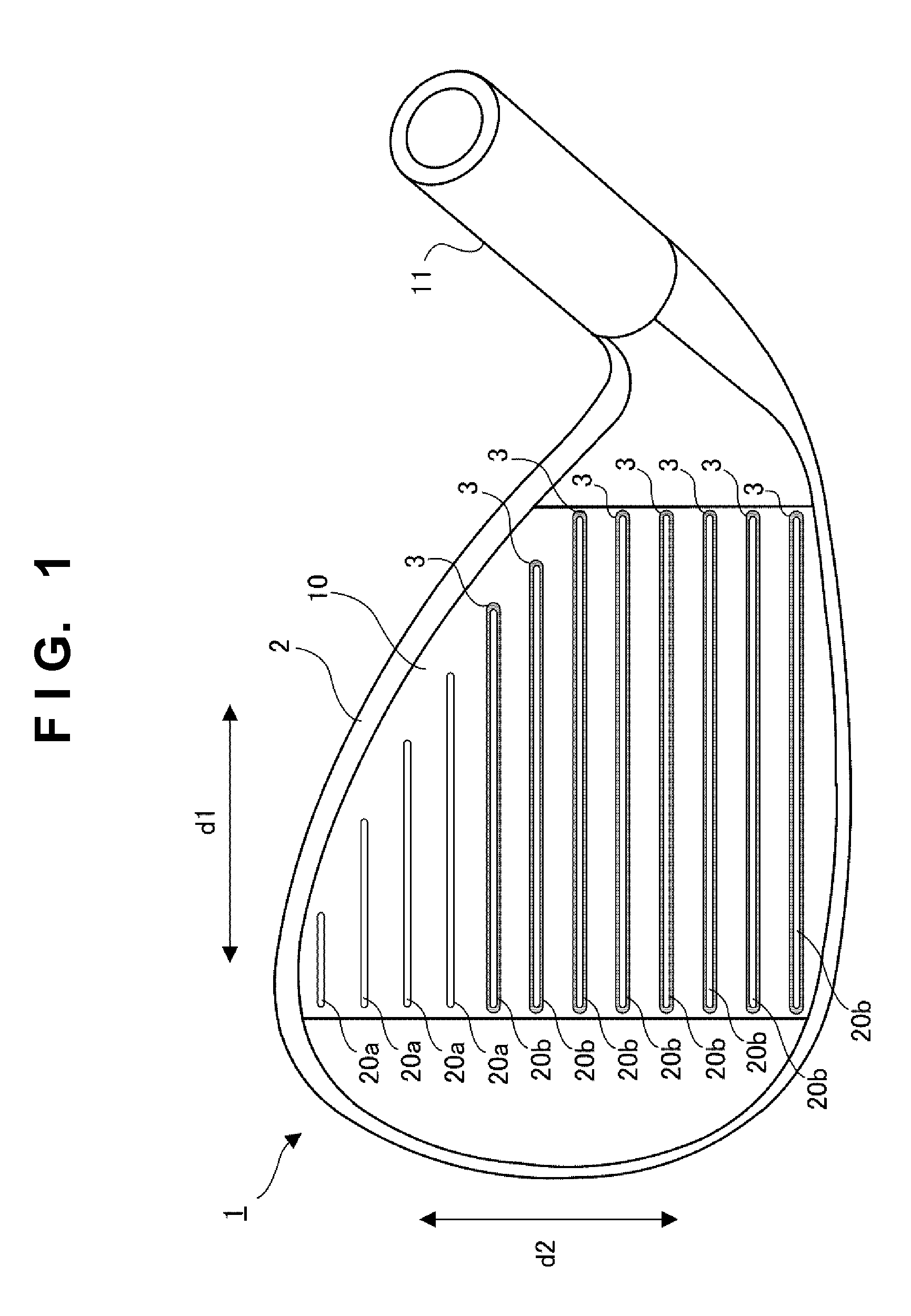
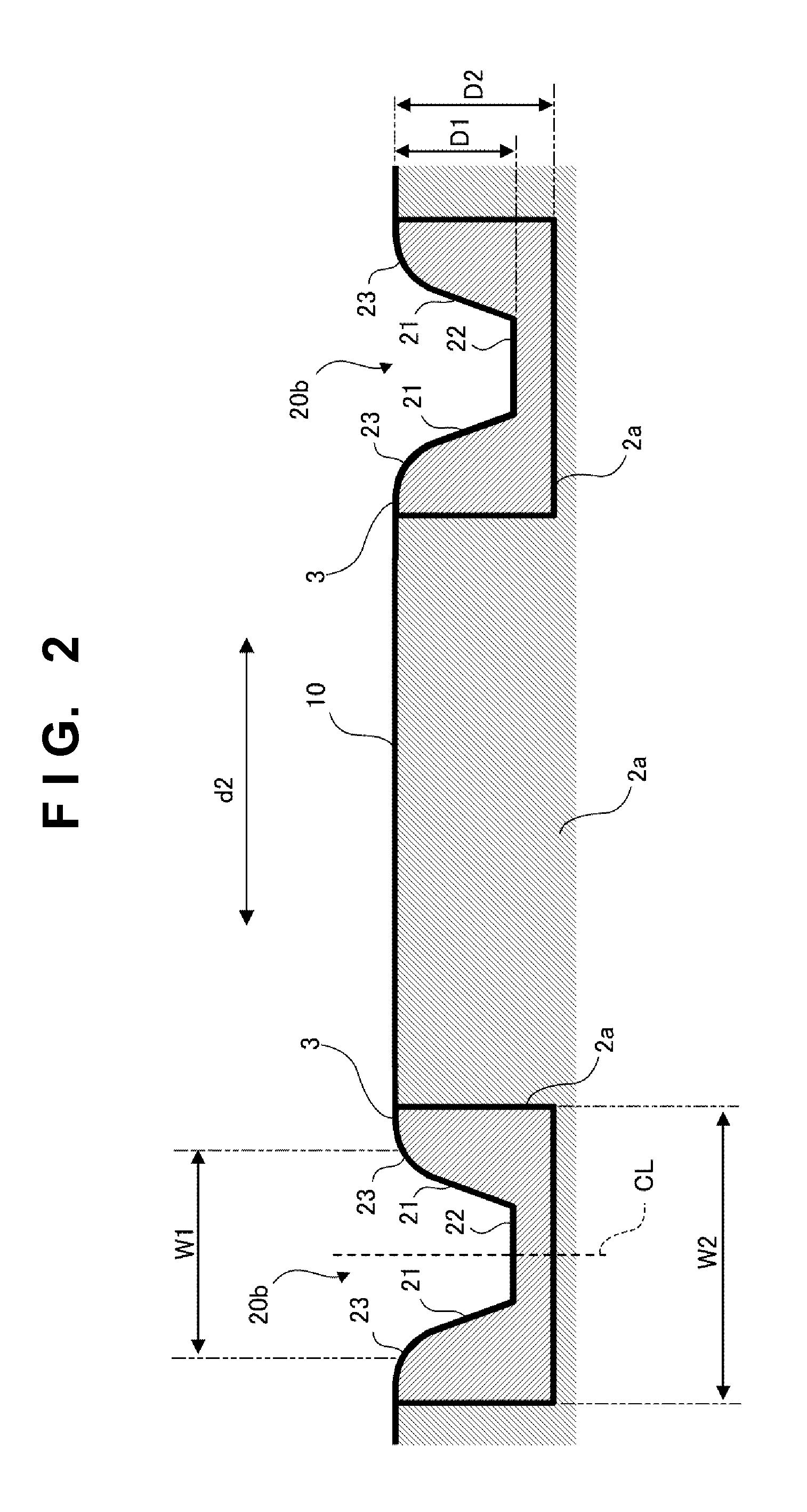
[0020]FIG. 1 is a perspective view of a golf club head 1 according to an embodiment of the present invention, and FIG. 2 is a sectional view of a face surface (striking surface) 10. Referring to FIGS. 1 and 2, a double-headed arrow d1 indicates the toe-to-heel direction, and a double-headed arrow d2 indicates a direction perpendicular to the direction d1. FIG. 2 is a sectional view of the face surface 10 along the direction d2.

[0021]This embodiment illustrates an example in which the present invention is applied to an iron golf club head. The present invention is suitable for an iron golf club head, and especially for middle iron, short iron, and wedge golf club heads. More specifically, the present invention is suitable for a golf club head with a loft angle of 30° (inclusive) to 70° (inclusive), and a head weight of 240 g (inclusive) to 320 g (inclusive). However, the present invention is also applicable to wood and utility (hybrid) golf club heads.

[0022]The golf club head 1 is fo...

second embodiment

[0043]Although one scoreline 20b is formed in one scoreline forming member 3 in the above-mentioned first embodiment, a plurality of scorelines 20b may be formed. In an example shown in FIG. 6A, two scorelines 20b are formed in a scoreline forming member 3A, in place of the scoreline forming member 3. With this arrangement, the total number of scoreline forming members 3A decreases, so the number of components of a golf club head 1 can be decreased. However, the exposed area of a main body member 2 in a face surface 10 reduces, so an impact feel deteriorates. Hence, when an impact feel is of great importance, it is preferable to form one scoreline 20b in one scoreline forming member 3A to reduce the thicknesses of the scoreline forming members 3A as much as possible. For example, a width W2 (see FIG. 2) of the scoreline forming member 3A is set twice or less a width W1 of the scoreline 20b.

[0044]Each recessed portion 2a may be a groove having at least one open end. In an example sho...

third embodiment

[0045]In the above-mentioned first embodiment, after the scoreline forming members 3 are fixed to the recessed portions 2a, and the scorelines 20b are formed in the scoreline forming members 3. In contrast to this, after scorelines 20b are formed in scoreline forming members 3 in advance, the scoreline forming members 3 having the scorelines already formed in them may be fixed to recessed portions 2a. A manufacturing method in the latter case will be described below.

[0046]FIG. 7 is a partial exploded view of a golf club head 1 according to this embodiment, and the golf club head 1 has the same arrangement except for a method of forming a golf club head 1 and scorelines 20b according to the above-mentioned first embodiment. Therefore, the same reference numerals as in the above-mentioned first embodiment denote the same constituent components in the third embodiment, and a description thereof will not be given. A different arrangement and manufacturing method will be described below....


PUM

PropertyMeasurementUnit
weightaaaaaaaaaa
radiusaaaaaaaaaa
depth D1aaaaaaaaaa

Abstract

This invention provides a method of manufacturing a golf club head including a face surface. This manufacturing method includes a step of forming a plurality of recessed portions in the face surface, included in a first member, to extend in the toe-to-heel direction, a fixing step of fixing, to the recessed portions, second members which are formed by a material different from that of the first member, and fill the recessed portions, and after the fixing step, a scoreline forming step of forming at least one scoreline in each of the second members, while not forming the scoreline in a portion, between the recessed portions, of the face surface of the first member.

Description

BACKGROUND OF THE INVENTION[0001]1. cl Field of the Invention[0002]The present invention relates to a golf club head.[0003]2. Description of the Related Art[0004]It is a common practice to form a plurality of parallel linear grooves in the face surface of a golf club head to extend in the toe-to-heel direction (for example, Japanese Patent Laid-Open Nos. 10-108927 and 7-163688). These grooves are called, for example, scorelines, marking lines, or face lines (they will be referred to as scorelines in this specification). The face surface has a considerable influence on the impact performance. For this reason, techniques of forming a golf club head using a plurality of types of materials to improve an impact feel and the spin amount or flight distance of a struck golf ball have been proposed (for example, Japanese Patent Laid-Open Nos. 10-108927, 7-163688, and 2001-293115).[0005]In general, if a golf club head is formed by a relatively soft material such as soft iron, an impact feel i...

Claims


Application Information

Patent Timeline
Patent Type & Authority Applications(United States)
IPC IPC(8): A63B53/04B23P17/00
CPCA63B53/04B23P17/00A63B2209/00A63B53/047A63B2053/0479Y10T29/49993A63B53/042A63B53/0445A63B53/0425A63B60/004
Inventor BAN, WATARU
Owner BRIDGESTONE SPORTS
Why Eureka
Try Eureka