Network system, controller, switch and traffic monitoring method

a traffic monitoring and network system technology, applied in the field of network systems, can solve the problems of increasing the deterioration of the network performance, the failure of statistical information of an important sort of packets, etc., and achieve the effect of high importance and without deterioration of the performan

Inactive Publication Date: 2013-11-14
NEC CORP
View PDF9 Cites 73 Cited by
  • Summary
  • Abstract
  • Description
  • Claims
  • Application Information

AI Technical Summary

Benefits of technology

[0047]The use of sFlow allows statistical processing (sampling) without deteriorating the performance in a high-speed network.
[0048]The use of OpenFlow allows statistical processing for important packets from which statistic information cannot be obtained by sFlow (that is, packets which have high importance but extremely-re

Problems solved by technology

One drawback of sFlow is that statistic information of an important sort of packets may fail to be obtained if the number of the packets does not exceed the threshold (that is, statistic information may be omitted for an important sort of packets, the number of which does not exceed the threshold); this results from the fact that sFlow obtains st

Method used


Image

  • Network system, controller, switch and traffic monitoring method
  • Network system, controller, switch and traffic monitoring method
  • Network system, controller, switch and traffic monitoring method

Examples


first exemplary embodiment

[0070]A first exemplary embodiment of the present invention is described below with reference to the attached drawings.

[0071][Basic Configuration]

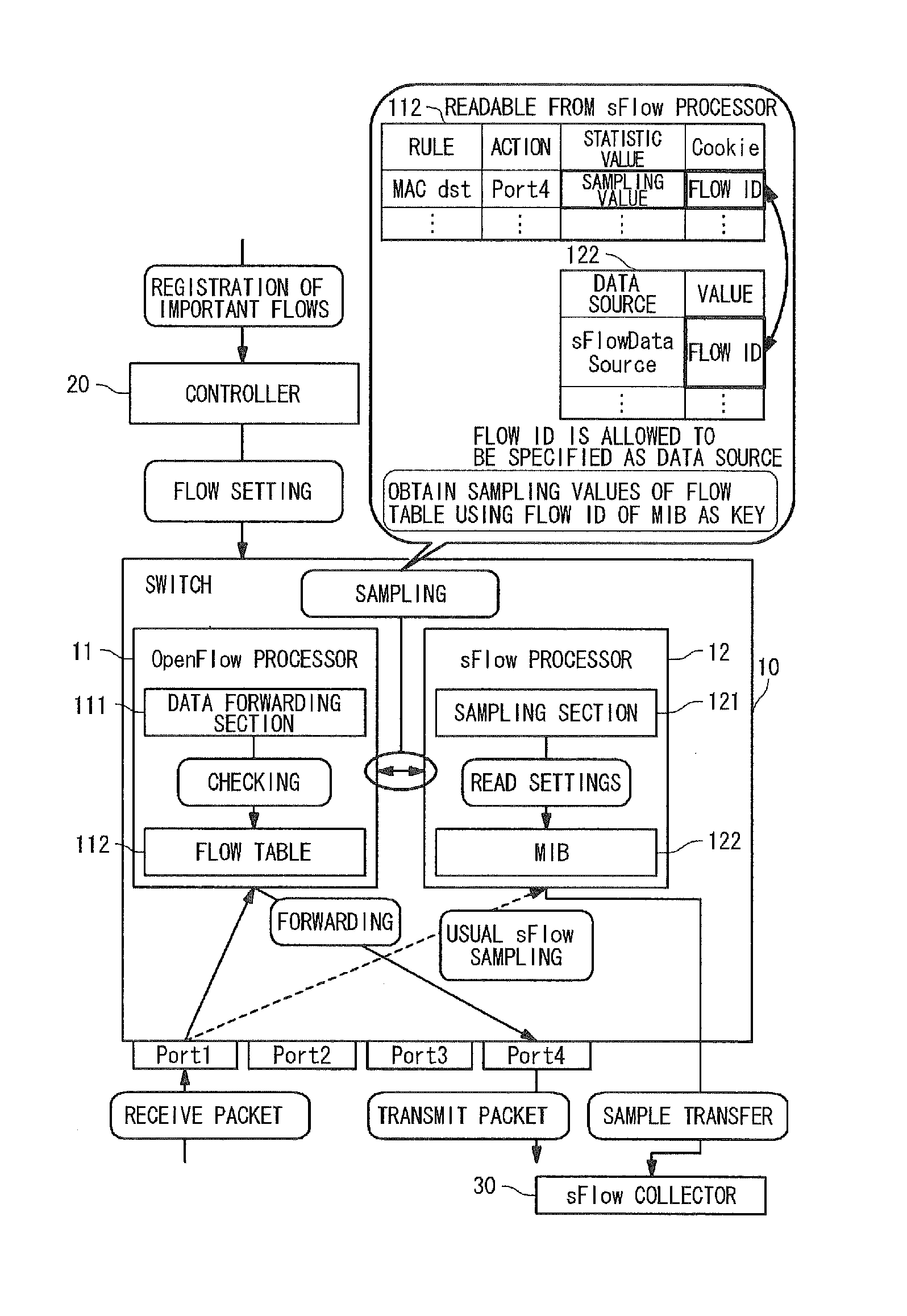
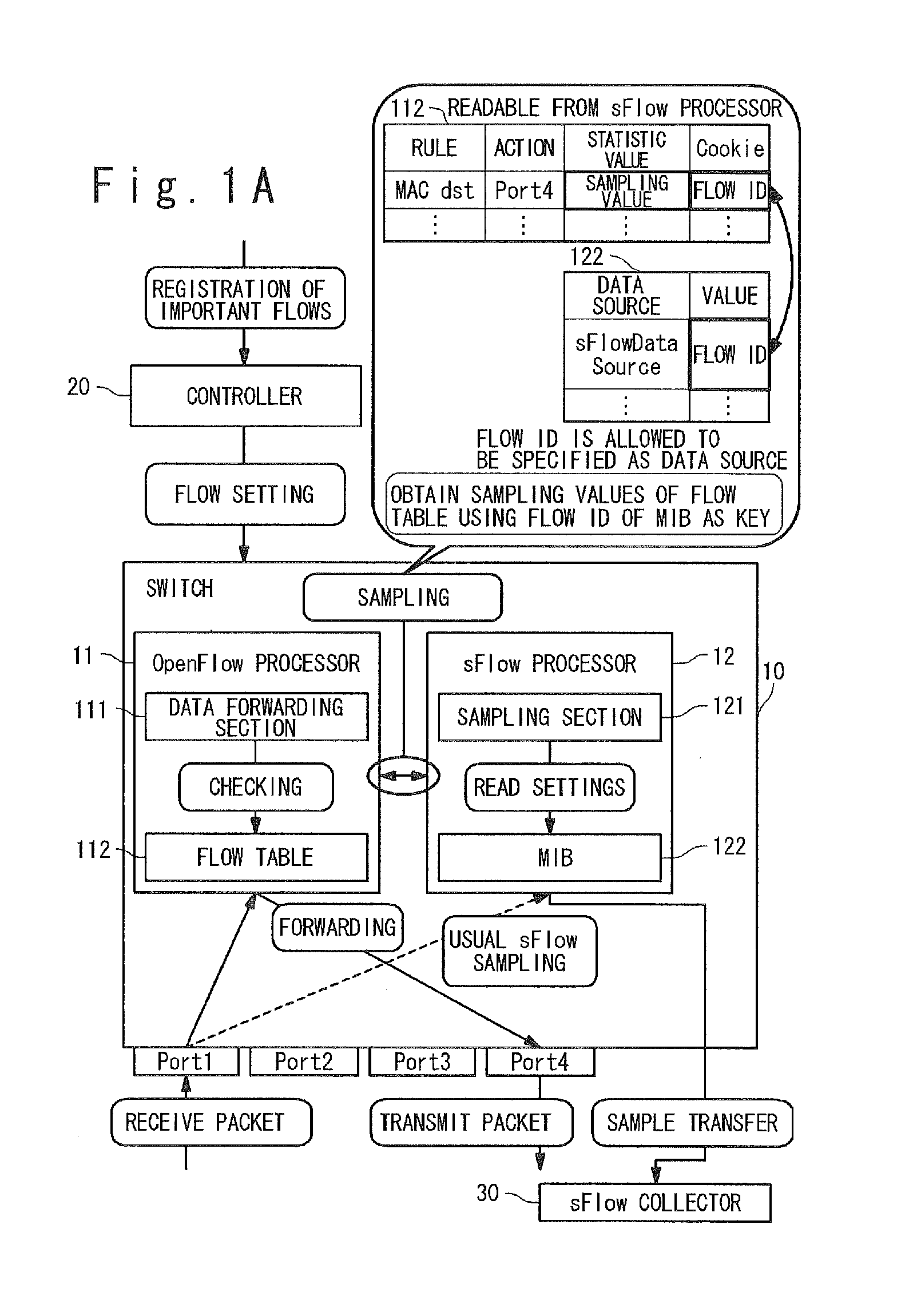
[0072]As shown in FIG. 1A, a network system according to the first exemplary embodiment of the present invention includes switches 10 (10-i, i=1 to n: n is the number of switches), a controller 20 and an sFlow collector 30.

[0073]The switches 10 (10-i, i=1 to n) and the controller 20 form an OpenFlow network. The switches witches 10 (10-i, i=1 to n) are nodes in the OpenFlow network. The controller 20 is connected with the switches 10 (10-i, i=1 to n) via secure channels. The sFlow collector 30 is connected with the switches 10 (10-i, i=1 to n) via usual lines and collects statistic information received from the switches 10 (10-i, i=1 to n).

[0074][Switch]

[0075]The switches 10 (10-i, i=1 to n) are adapted to OpenFlow.

[0076]Each of the switches 10 (10-i, i=1 to n) includes an OpenFlow processor (forwarding section) 11 and an sFlow processor (...

second exemplary embodiment

[0168]A second exemplary embodiment of the present invention is described below with reference to the attached drawings. In this exemplary embodiment, in each of the switches 10 (10-i, i=1 to n), when the OpenFlow processor 11 compares the entries of the flow table with a received packet, the sFlow processor 12 informs the OpenFlow process 11 of flow identifiers specified as data sources of the MIB 122 and receives packets which match the entries containing the flow identifiers as a response. The sFlow processor 12 performs sampling according to sFlow for these packets.

[0169][Configuration in this Exemplary Embodiment]

[0170]As shown in FIG. 5A, the configuration of the network system according to the second exemplary embodiment of the present invention is basically identical to that of the network system according to the first exemplary embodiment of the present invention.

[0171]As shown in FIG. 5A, the network system according to the second exemplary embodiment of the present invent...


PUM


Abstract

Fine traffic monitoring is achieved in a network in which sFlow and OpenFlow are combined. Specifically, flow identifiers (flow IDs) for identifying flows (or groups of packets) are prepared, and the flow identifiers are stored in entries of flow tables to allow sFlow agents to specify the flow identifiers as data sources. Specifically, the flow identifiers are stored in cookies of entries registered in flow tables of switches from a controller, and operations are performed for received packets matching the rules of the entries in accordance with the actions defined in the entries. In the switches, the flow identifiers specified as data sources in the MIBs used in sFlow are obtained and statistic information of packets matching the entries is obtained on the basis of the flow identifiers.

Description

TECHNICAL FIELD[0001]The present invention is related to a network system, more particularly, to a traffic monitoring method in a network system.BACKGROUND ART[0002]Traffic monitoring is one important factor for ensuring a QoS (quality of service) in the network operation.[0003]One major traffic monitoring method is “sFlow” (RFC3176), which is a technique for monitoring the traffic of switches, routers and the like in a Gigabit network.[0004]The sFlow is a traffic management technique based on packet sampling, in which a specific percentage of data to be monitored are collected to generate traffic information by a statistic approach. The sFlow has been open to the public and provided free of charge as IETF (Internet engineering task force) RFC (request for comment) 3176, since September 2001.[0005][sFlow][0006]An overview of monitoring based on sFlow is described below.[0007]In a network monitored by sFlow, an sFlow collector which operates outside an NW device (a network connection...

Claims


Application Information

Patent Timeline
IPC IPC(8): H04L12/56H04L45/42
CPCH04L47/24H04L43/026H04L41/5019Y02D30/50H04L41/40H04L43/20
Inventor KAWAI, RYOSUKE
Owner NEC CORP
Why Eureka
Try Eureka