Bag hanger

Inactive Publication Date: 2013-11-21
HACHIMAN KASEI
View PDF11 Cites 3 Cited by
  • Summary
  • Abstract
  • Description
  • Claims
  • Application Information

AI Technical Summary

Benefits of technology

[0009]The present invention can solve the above-mentioned problems, by providing a bag han

Problems solved by technology

However, the bag hanger stated in the Patent documents 1 has such problem that the bag on the hook can be easily rotated and cannot be stabled, since the hook part of the bag hanger can be rotated.
Moreover

Method used


Image

  • Bag hanger
  • Bag hanger
  • Bag hanger

Examples


Example

THE FORM TO IMPLEMENT THE INVENTION

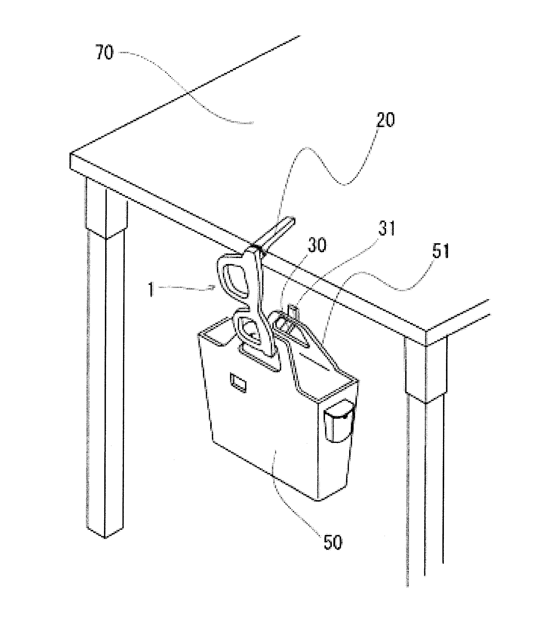
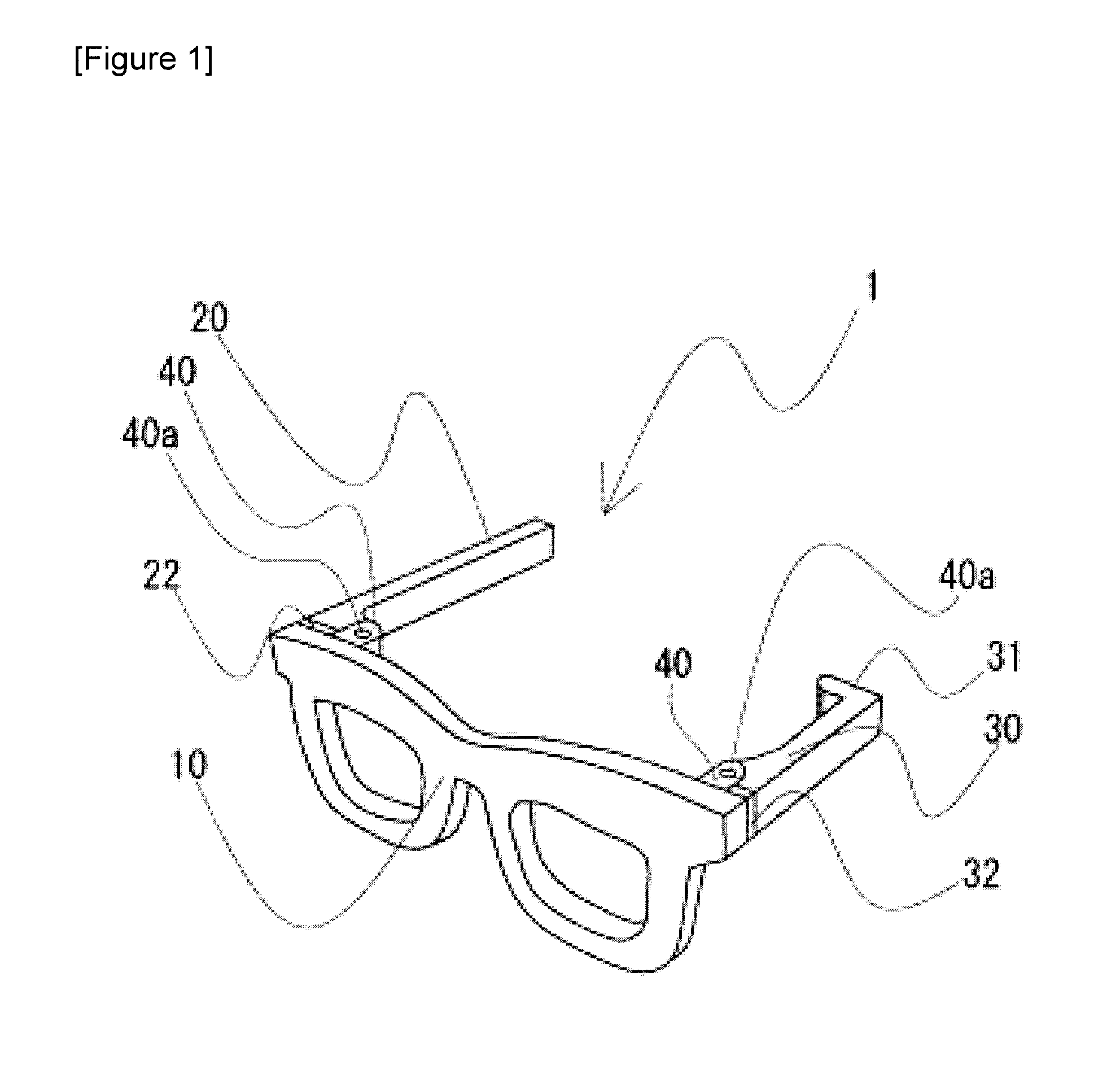
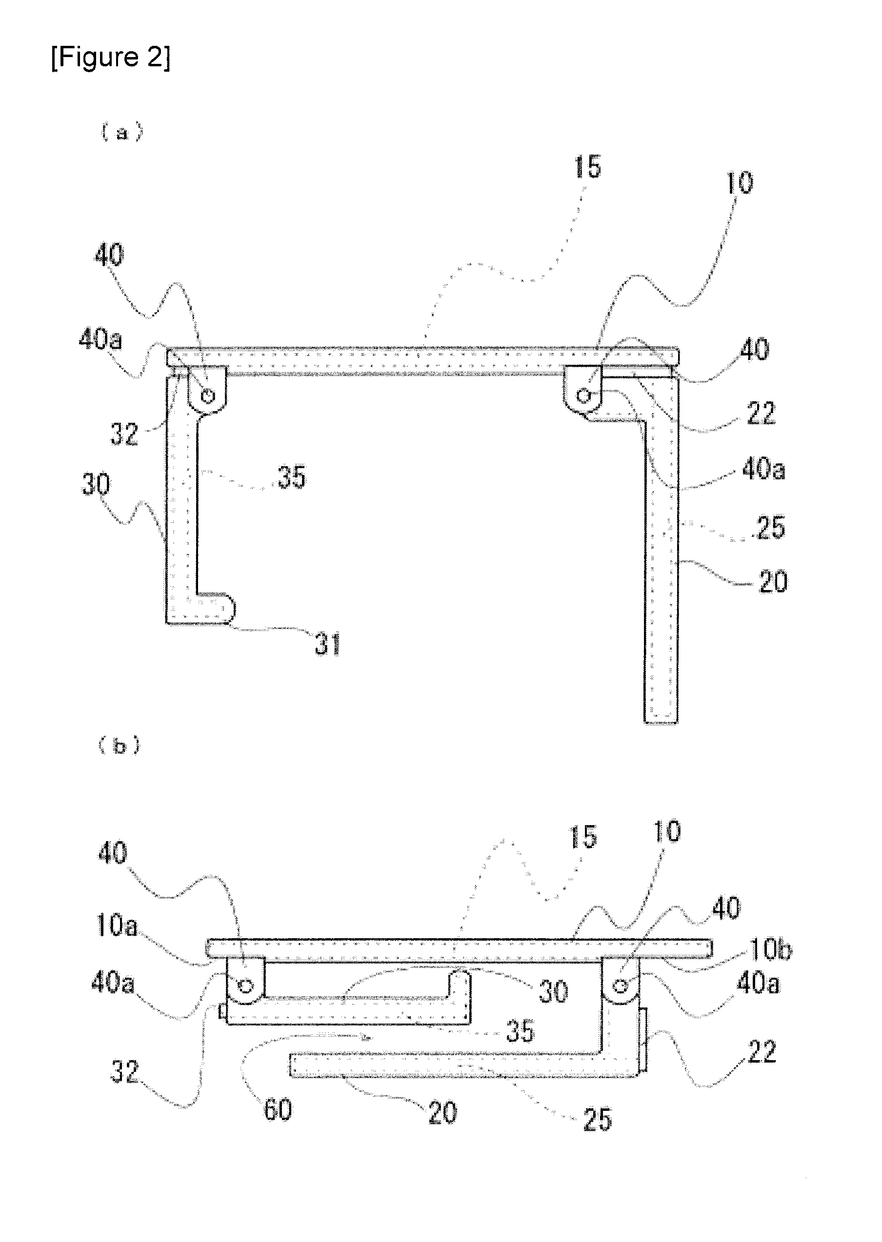
[0021]Here is an explanation about the invention in detail while referring to FIG. 1-5. In addition, the present invention shall not be limited to the specific example of use shown in the drawing, but could be variously changed depending on the purpose and the use.

[0022]The bag hanger involved in this invention consists of a connecting part, a support part, which is connected to the above-mentioned connecting part and stands on one end of the above-mentioned connecting part perpendicular to the above-mentioned connecting part and is for placement on a table board, and a hook part, which is connected to the above-mentioned connecting part and stands on the other end of the above-mentioned connecting part facing the above-mentioned support part and perpendicular to the above-mentioned connecting part, and is for hanging the bag, while, the above-mentioned connecting part, the above-mentioned support part and the above-mentioned hook part are so chara...


PUM


Abstract

[Problem] To provide a bag hanger capable of stably and reliably securing a bag without stressing the handle of the bag.
[Solution] The bag hanger (1) is obtained from: a connecting part (10); a support part (20) that stands on one end of the connecting part (10) perpendicular to the connecting part (10) and is for placement on a table board; and a hook part (30) that stands on the other end of the connecting part (10) facing the support part (20) and perpendicular to the connecting part (10), and is for hanging the bag. The connecting part (10), support part (20) and hook part (30) are formed by covering rod-shaped metal cores with a soft material capable of elastic deformation. On the end of the hook part (30), a catch (31) is formed. The support part (20) and the hook part (30) are connected rotatably to the connecting part (10) by hinge parts. The soft material is preferably a thermoplastic elastomer.

Description

TECHNICAL FIELD[0001]The present invention relates to a bag hanger, in more details, a bag hanger to be hooked on the table board of such as a table or a desk and is used for hanging and holding the back.BACKGROUND TECHNOLOGY[0002]Considering a problem to be troubled with the place for bags in a restaurant, a conference room, etc., a bag hanger has been devised by hanging and holding a bag under the table (for example, refer to the Patent documents 1).[0003]This bag hanger hangs a bag by hooking the handle of a bag on the hook, and a support part of the hook is laid and fixed on the table board of such as a table.[0004]Hence the hook part of the bag hanger can freely rotate around the connecting part, this bag hanger has the advantage to be able to change the direction of the hook part freely, therefore, the bag and the hook will never be interfered by an obstacle or a lateral plate of the table or the desk located near at hand.CONVENTIONAL TECHNOLOGY DOCUMENT[0005]Patent document[0...

Claims


Application Information

Patent Timeline
IPC IPC(8): A47G29/093
CPCA47G29/093A47G29/083
Inventor TAKAGAKI, MIYOKO
Owner HACHIMAN KASEI
Why Eureka
Try Eureka