Supercharge Your Innovation With Domain-Expert AI Agents!

Interference cancellation system

Active Publication Date: 2013-11-21
L 3 COMM CORP +1
View PDF14 Cites 32 Cited by
  • Summary
  • Abstract
  • Description
  • Claims
  • Application Information

AI Technical Summary

Benefits of technology

The patent describes a system and method for canceling out interference signals in order to determine a signal of interest (SOI) in a wireless communication system. The system includes an RF subsystem and an optical subsystem. The RF subsystem receives the interference signal and the combined interference and SOI signal, and converts them to optical signals using a direct modulation technique. The optical subsystem then applies time delays and attenuation to the optical signals using tunable lasers. The system generates control signals to minimize the power level of the combined RF signal. The optical subsystem includes a plurality of optical processing lines and tunable CW lasers to select which delay lines to use. The system can cancel out interference signals and improve the quality of the SOI signal.

Problems solved by technology

Electromagnetic interference, which may also be referred to as radio frequency (RF) interference, may be a disturbance that affects electrical circuits and / or antennas due to electromagnetic induction or electromagnetic radiation being present when attempting to transmit and / or receive a signal of interest.
For example, an interfering radio signal may be present when attempting to receive a radio signal of interest.
The interference caused by the interfering signal may prevent, obstruct, or otherwise degrade the ability of a receiver from successfully receiving and interpreting the signal of interest.

Method used


Image

  • Interference cancellation system
  • Interference cancellation system
  • Interference cancellation system

Examples


Embodiment Construction

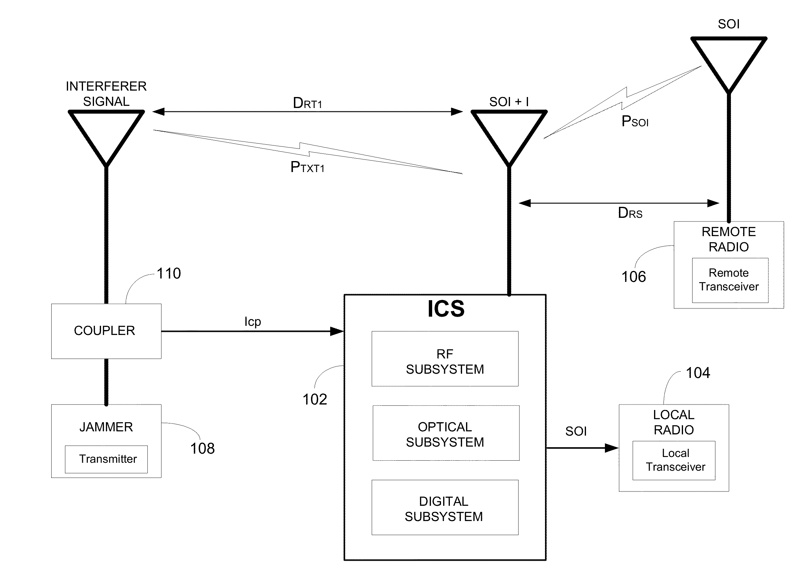
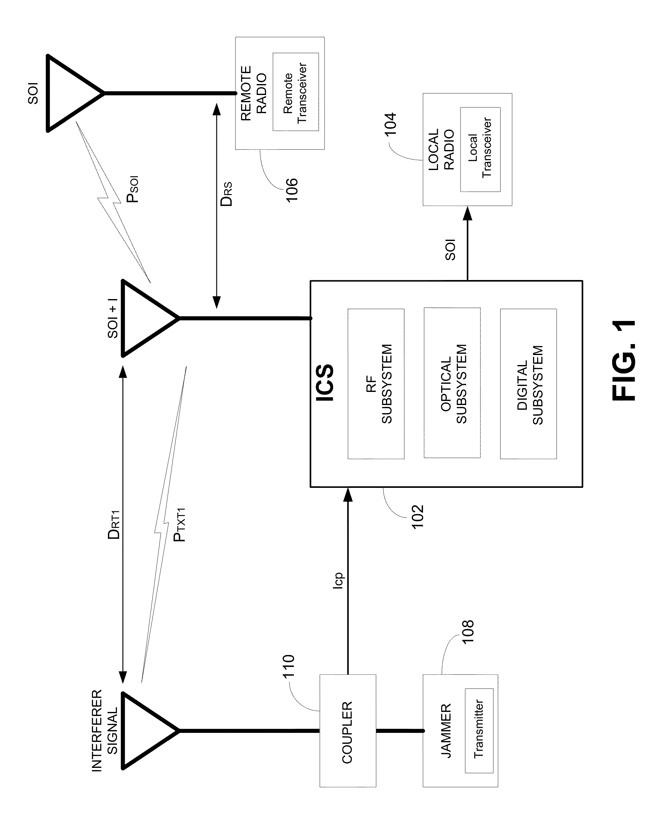
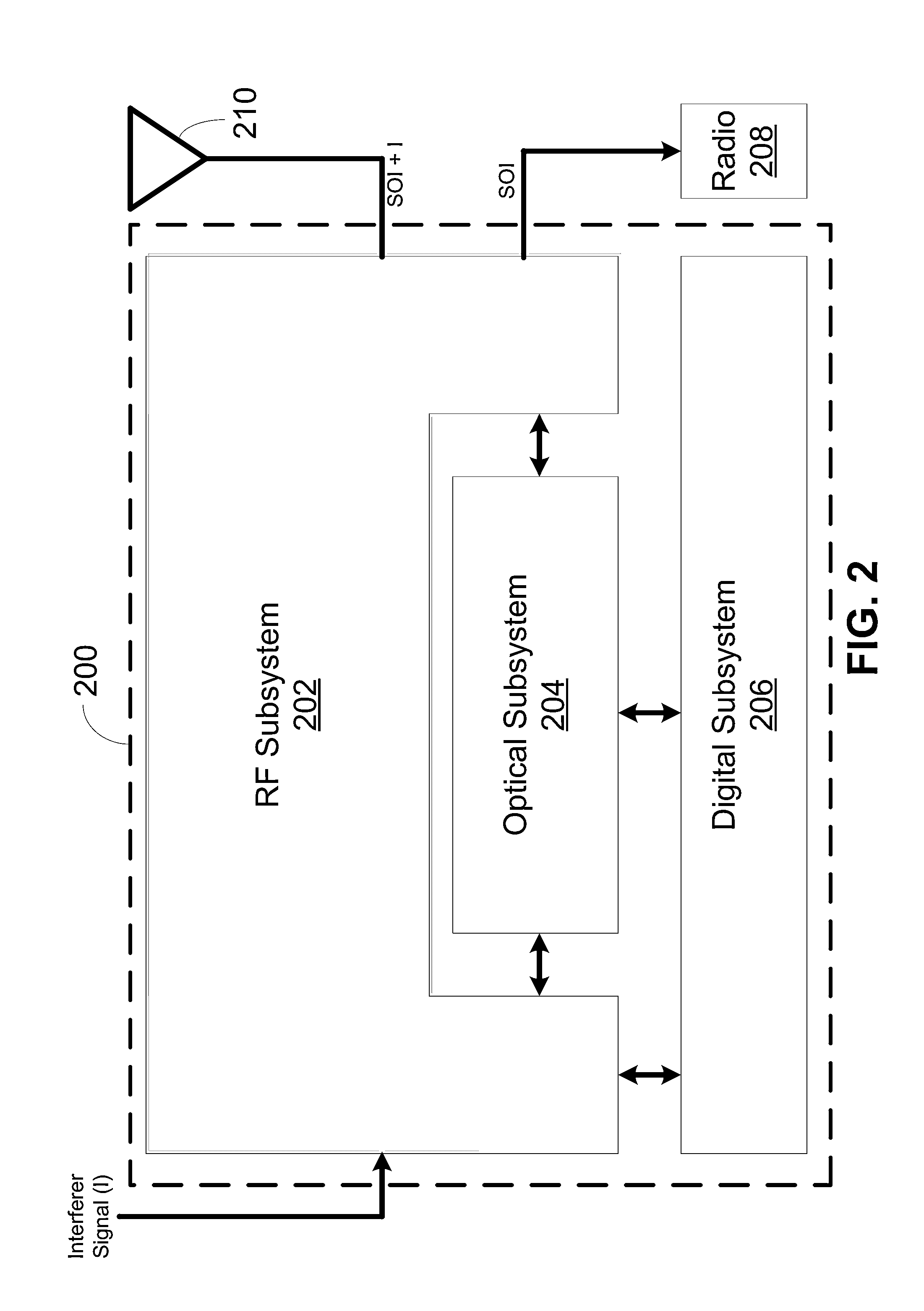
[0031]Disclosed herein are systems and methods for cancelling interference from a received signal in order to properly detect a signal of interest. The method may include receiving a combined signal of interest and interference signal. The method may further include receiving / determining a sample of the interference signal. The combined signal of interest and interference signal and / or the interference signal may be variably attenuated and / or variably delayed in the RF domain prior to being transformed to the optical domain, for example to increase the speed of an interference cancellation process prior to optical interference cancellation. The RF variable attenuation and / or variable delay may increase the maximum operational range(s) of delays and / or gain ratios between an interference signal received with the signal of interest and the interference signal received separately from the signal of interest. The interference signal may be converted to the optical domain and optically p...


PUM


Abstract

Systems and methods for cancelling interference from a received signal in order to properly detect a signal of interest are disclosed. A combined signal of interest plus interference signal may be received. A copy or sample of the interference signal may be determined. The interference signal and the combined signal of interest plus interference signal may be converted to the optical domain. The interference signal may be optically phase shifted by −180 degrees, which may result in an optically inverted interference signal. The optically inverted interference signal may be variably optically attenuated and / or variably optically time delayed, for example based on a detected output power of an optical subsystem of the interference cancellation system. As a result, interference cancellation of the interference signal from the combined signal of interest plus interference signal may be achieved, resulting in 50 dB or more of cancellation of the interference signal.

Description

CROSS-REFERENCE TO RELATED APPLICATIONS[0001]This application claims the benefit of U.S. Provisional Patent Application No. 61 / 649,715, filed May 21, 2012; U.S. Provisional Patent Application No. 61 / 649,843, filed May 21, 2012; and U.S. Provisional Patent Application No. 61 / 649,856, filed May 21, 2012; the contents of which are hereby incorporated by reference in their entirety.[0002]This application may include subject matter that is related to subject matter included in U.S. patent application No. [Attorney Docket No. LTEL_MI_US 01], filed May 21, 2013 and U.S. patent application No. [Attorney Docket No. LTEL_RI_US 01], filed May 21, 2013.BACKGROUND[0003]Electromagnetic interference, which may also be referred to as radio frequency (RF) interference, may be a disturbance that affects electrical circuits and / or antennas due to electromagnetic induction or electromagnetic radiation being present when attempting to transmit and / or receive a signal of interest. For example, an interfe...

Claims


Application Information

Patent Timeline
IPC IPC(8): H04B1/10
CPCH04B1/10H04B1/109H04K3/228H04B1/1027H04K3/20H04B10/00H04B2210/006H04B17/318H04B17/336H04L43/16H04B10/07955H04B10/2507H04B10/2575
Inventor KPODZO, ELIAS BONAVENTUREHOLLAND, ROBERTDENG, YANHUAPRUCNAL, PAULMCCANDLESS, ANDREWDOURBAL, PAUL
Owner L 3 COMM CORP
Features
  • R&D
  • Intellectual Property
  • Life Sciences
  • Materials
  • Tech Scout
  • Unparalleled Data Quality
  • Higher Quality Content
  • 60% Fewer Hallucinations
Learn More