Fluidic and electrical interface for microfluidic chips

Active Publication Date: 2013-11-28
METTLER TOLEDO THORNTON
View PDF2 Cites 10 Cited by
  • Summary
  • Abstract
  • Description
  • Claims
  • Application Information

AI Technical Summary

Benefits of technology

[0015]Benefits and advantages of the present invention include, but are not limited to, providing a microfluidic chip interface for reliably and reproducibly flushing fluids from external sources through the wells of the microchip to external waste containers, in a manner that prevents fluid films from spreading acr

Problems solved by technology

Although certain substances within a sample fluid may be efficiently separated for analysis using conventional microfluidic chips for capillary electrophoresis, the handling, timing and delivery of

Method used


Image

  • Fluidic and electrical interface for microfluidic chips
  • Fluidic and electrical interface for microfluidic chips
  • Fluidic and electrical interface for microfluidic chips

Examples


Embodiment Construction

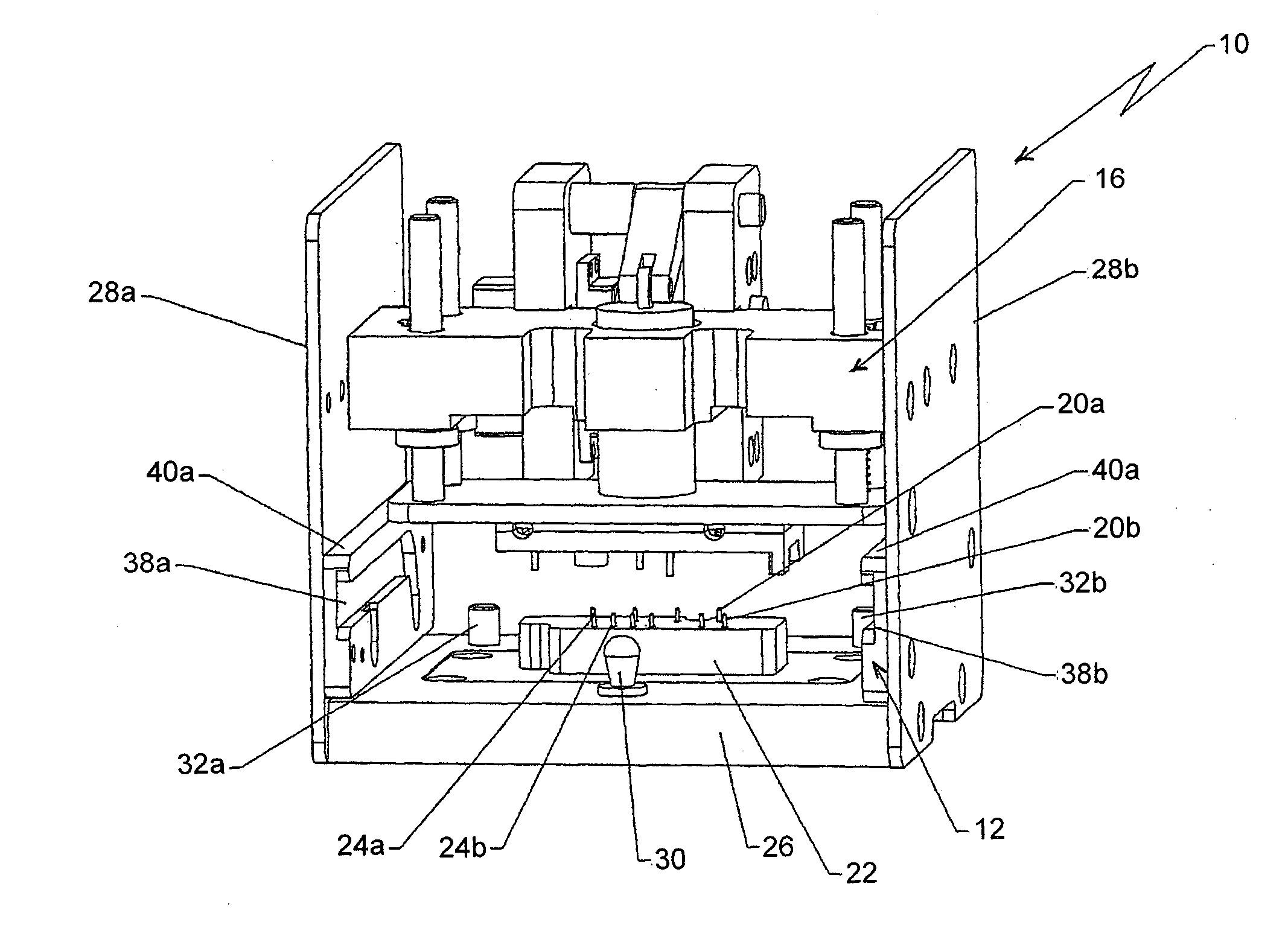
[0024]Briefly, embodiments of the present invention include a fluidic and electrical interface effective for transferring fluids from external fluid sources through microfluidic channels in a microfluidic chip to external waste containers, and for providing electrical contact to the chip for enabling measurements to be made on the fluid components. As used herein, the terms chip and microchip are intended to mean a microfluidic chip.

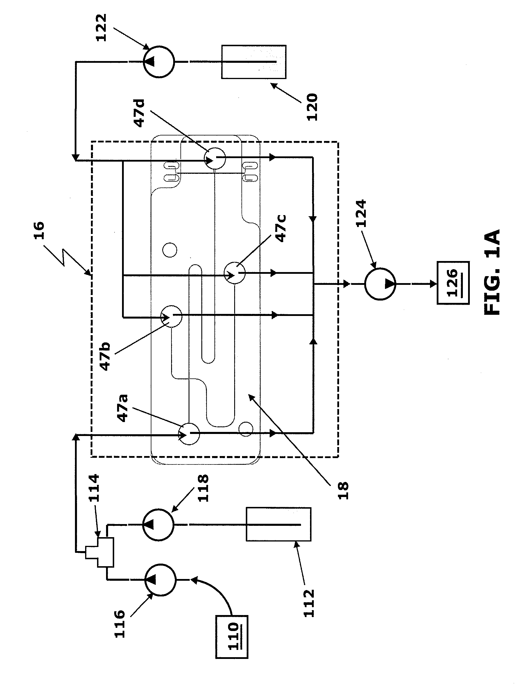
[0025]Reference will now be made in detail to the present embodiments of the invention, examples of which are illustrated in the accompanying drawings. In what follows, similar or identical structure will be identified using identical reference characters. Turning now to FIG. 1A, a schematic representation of an embodiment of a fluid manifold assembly including fluid manifold, 16, of the present invention effective for filling and flushing (dispensing fluid to) fluid well, 47a, of microchip, 18, with sample solution from source, 110, and with an internal...


PUM

PropertyMeasurementUnit
Distanceaaaaaaaaaa

Abstract

A microfluidic chip interface for providing fluid communication with external fluid sources and external fluid waste containers, and for providing electrical contact with voltage sources and voltage and current measuring devices, is described. The microchip is first placed into electrical communication with at least one electrical source and at least one electronic measurement device, and reversibly secured in place. Chosen fluids are provided into the microchip and directed through the chip using a fluid manifold having dispensing tubes and fluid aspiration tubes, which is brought into the vicinity of the secured microchip. The distance between the fluid manifold and the microchip is chosen such that the injection tubes are located within wells in the microchip connected to microfluidic channels, and the aspiration tubes are located near the surface of the microchip in the vicinity of the wells such that fluid spillage onto the surface of the microchip during fluid transfer is avoided. The fluid manifold is removed from fluid communication with the microchip during electrical measurements.

Description

CROSS-REFERENCE TO RELATED APPLICATIONS[0001]The present application claims the benefit of U.S. Provisional Patent Application No. 61 / 559,497 for “Fluidic And Electrical Interface For Microfluidic Chips” which was filed on Nov. 14, 2011, the entire contents of which is hereby specifically incorporated by reference herein for all that it discloses and teaches.FIELD OF THE INVENTION[0002]The present invention relates generally microfluidic chips suitable for capillary electrophoresis as an example and, more particularly, to a fluidic and electrical interface effective for transferring fluids from external fluid sources through a microfluidic chip to external waste containers, and for providing electrical contact to the microfluidic chip to enable measurements to be made on the fluids.BACKGROUND OF THE INVENTION[0003]Microfluidic chips find use in many areas such as fluid mixing for chemical reactions, cell sorting, and electrophoresis, as examples, and often have both electrical termi...

Claims


Application Information

Patent Timeline
IPC IPC(8): G01N27/447B81B1/00
CPCG01N27/44791B81B1/00B01L3/502715B01L3/50273B01L9/527B01L2300/0816B01L2400/0421B01L2400/049G01N35/00069Y10T29/49117
Inventor PALMER, JAMES T.DEKLEVA, PHILIPPE M.
Owner METTLER TOLEDO THORNTON
Why Eureka
Try Eureka