Filtration container

a technology of filtration container and filtration chamber, which is applied in the field of filtration container, can solve the problems of high percentage loss of final yield, difficult to complete sample recovery, and difficult to complete and define sample recovery

Active Publication Date: 2013-11-28
SARTORIUS STEDIM BIOTECH GMBH
View PDF3 Cites 5 Cited by
  • Summary
  • Abstract
  • Description
  • Claims
  • Application Information

AI Technical Summary

Benefits of technology

[0017]In accordance with a further preferred embodiment of the invention, the base is planar and has a rounded transition to the connection walls. Due to the rounded transition, runoff of the retentate towards the deepest point of the retentate container is favored and complete suction with a pipette is improved.
[0020]In accordance with a further preferred embodiment of the invention, at least the retentate chamber is formed from a chemically inert material, in particular from the polymer polystyrene. Polystyrene has the advantage that it is chemically inert and has no protein-binding properties. Due to the design according to the invention, the collection of the concentrated sample or of the retentate in a very small volume space, which is additionally chemically inert, is made possible.

Problems solved by technology

This means that losses of just a few microliters lead to high percentage losses of the final yields.
Although this known device has proven its worth in principle, it has been found that complete sample recovery is very difficult.
With this device too, a complete and defined sample recovery has proven to be very difficult.

Method used


Image

  • Filtration container
  • Filtration container
  • Filtration container

Examples


Embodiment Construction

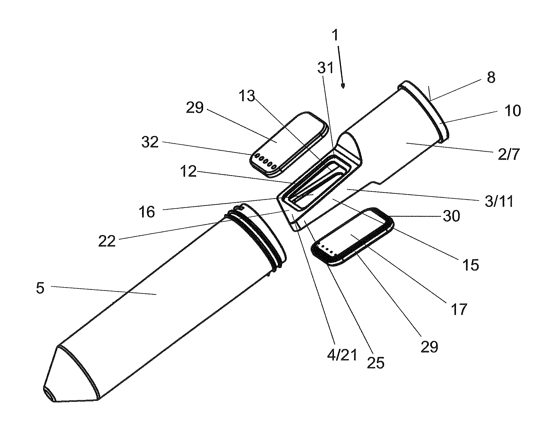
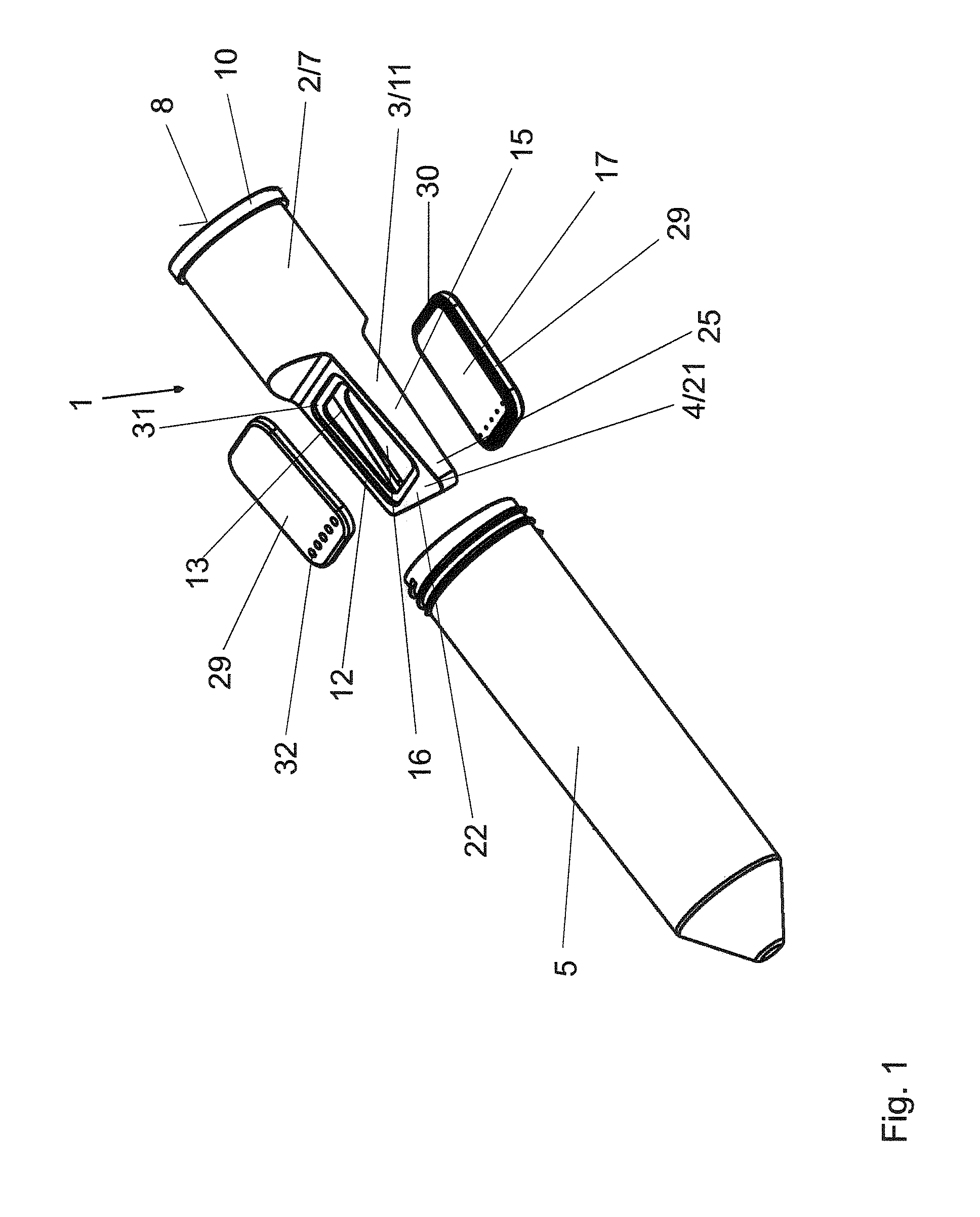
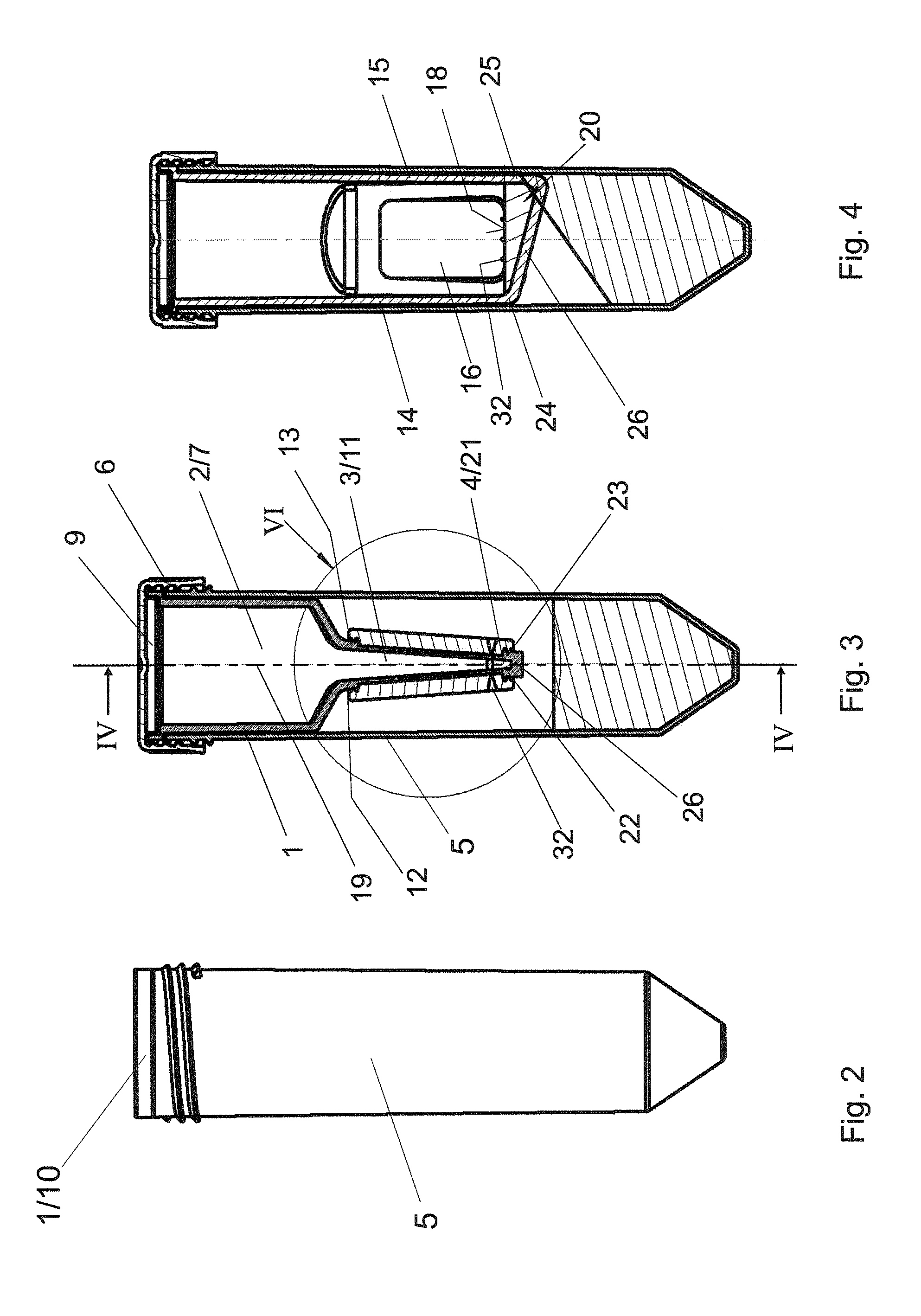
[0032]A filtration container 1 basically consists of an upper portion 2, a central portion 3, and from a lower portion 4.

[0033]The filtration container 1 can be inserted into a filtrate recovery tube 5, which can be closed by a closure cap 6. The upper portion 2 forms a sample container 7, which is hollow-cylindrical and has an inlet opening 9 on its upper end face 8.

[0034]At its upper end, the upper portion 2 has a peripheral bead 10, which is used as a stop relative to the filtrate recovery tube 5. At its lower end facing away from the upper end face 8, the upper portion 2 transitions into the central portion 3. The central portion 3 tapers downwardly in the vertical direction and forms a filtration chamber 11, which has two mutually opposed main walls 12, 13 running downwardly towards one another and also two gusset-like connection walls 14, 15 connecting said main walls at the lateral edges thereof. A filter window 16 for receiving a planar membrane filter 17 is arranged in each...


PUM

PropertyMeasurementUnit
angle of inclinationaaaaaaaaaa
volumeaaaaaaaaaa

Abstract

A filtration container for concentration of macromolecules is insertable into a filtrate recovery tube (5) and has an upper portion (2), a central portion (3) axially adjoining the upper portion (2), and a lower portion (4) axially adjoining the central portion (3). The upper portion (3) forms a hollow-cylindrical sample container (7) with an inlet opening (9) on its upper end face (8). The downwardly tapering central portion (3) has a filtration chamber (11) with two mutually opposed main walls (12, 13) running down toward one another. At least one of the main walls (12, 13) has a filter window (16) for receiving a planar membrane filter (17). The lower portion (4) forms a retentate chamber (21) adjoining the lower edge (18) of the filter window (16) A base (26) of the retentate chamber (21) slopes down on one side laterally.

Description

BACKGROUND[0001]1. Field of the Invention[0002]The invention relates to a filtration container, in particular for concentration of macromolecules, said filtration container being insertable into a filtrate recovery tube and comprising an upper portion, a central portion axially adjoining the upper portion, and a lower portion axially adjoining the central portion, of which[0003]the upper portion forms a sample container, which is hollow-cylindrical and has an inlet opening on its upper end face,[0004]the downwardly tapering central portion a filtration chamber, which has two mutually opposed main walls running downwardly towards one another and also two gusset-like connection walls connecting said main walls at the lateral edges thereof, at least one of the main walls having a filter window for receiving a planar membrane filter, and[0005]the lower portion forms a retentate chamber adjoining the lower edge of the filter window, the defining main walls and connection walls of said re...

Claims


Application Information

Patent Timeline
Patent Type & Authority Applications(United States)
IPC IPC(8): B01D35/30
CPCB01D35/30B01L3/5021B01L2300/0681G01N2001/4088
Inventor BIDDELL, CHRISTOPHER
Owner SARTORIUS STEDIM BIOTECH GMBH
Why Eureka
Try Eureka