Variable pitch resistance coil heater

a coil heater and variable pitch technology, applied in the field of electric heaters, can solve problems such as bulky structur

Active Publication Date: 2013-11-28
WATLOW ELECTRIC MFG
View PDF15 Cites 34 Cited by
  • Summary
  • Abstract
  • Description
  • Claims
  • Application Information

AI Technical Summary

Benefits of technology

[0005]In one form, a heater includes a resistance coil assembly, an insulating material surrounding the resistance coil assembly, and a sheath surrounding the insulating material. The resistance coil assembly defines a first end portion having a first conducting pin and a second end portion having a second conducting pin. A resistance coil is disposed between the first end portion and the second end portion. The resistance coil defines a plurality of different pitches between the first end portion and the second end portion. The plurality of different pitches provide a variable watt density such that a predetermined temperature profile is provided along the sheath.
[0006]In another form, an electric heat exchanger includes a heater. The heater includes a resistance coil assembly, an insulating material surrounding the resistance coil assembly, and a sheath surrounding the insulating material. The resistance coil assembly defines a first end portion having a first conducting pin and a second end portion having a second conducting pin. A resistance coil is disposed between the first end portion and the second end portion. The resistance coil defines a plurality of different pitches between the first end portion and the second end portion. The plurality of differe

Problems solved by technology

To increase the heat capacity rate of the heat exchanger, more tubular heaters may be provided in the heat exchanger, resulting in a bulky structure.
Moreover, heat exchangers usi

Method used


Image

  • Variable pitch resistance coil heater
  • Variable pitch resistance coil heater
  • Variable pitch resistance coil heater

Examples


Embodiment Construction

[0022]The following description is merely exemplary in nature and is not intended to limit the present disclosure, application, or uses.

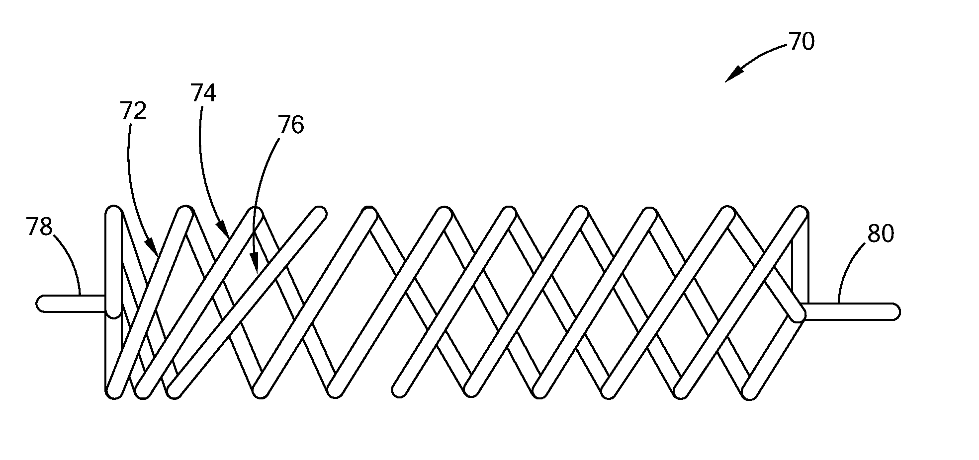
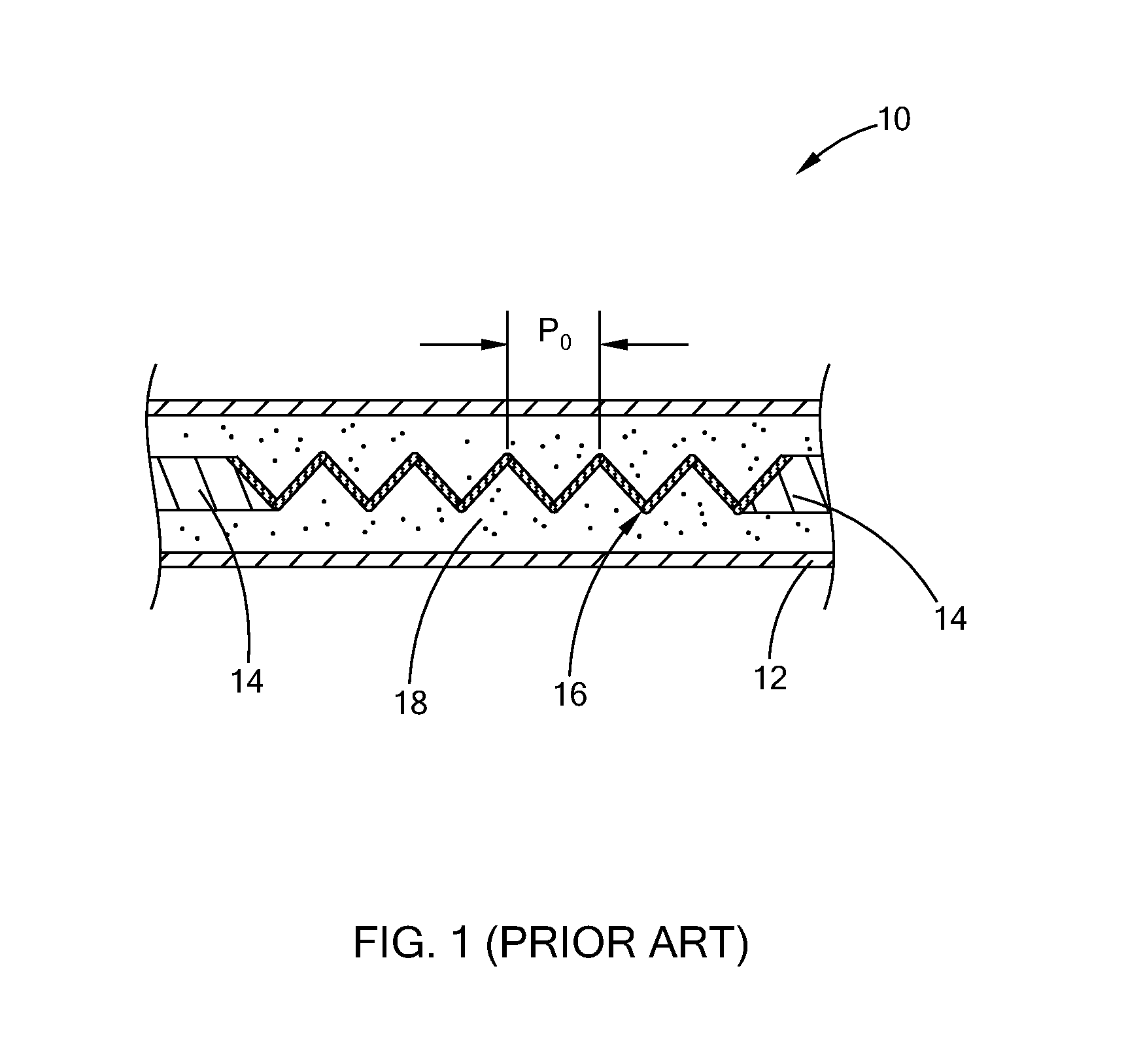
[0023]Referring to FIG. 1, a typical tubular heater 10 generally includes a tubular outer sheath 12, a pair of conducting pins 14 protruding from opposing ends of the tubular outer sheath 12, a resistance coil 16 disposed between the conducting pins 14, and an insulating material 18. The resistance coil 16 generally includes resistance-type metal alloy and is formed into a helical coil shape. The resistance coil 16 generally has a constant pitch P0 along the length of the resistance coil 16 to provide uniform heating along the length of the tubular outer sheath 12. The insulating material 18, such as magnesium oxide, is provided inside the tubular outer sheath 12 to surround and electrically insulates the resistance coil 16.

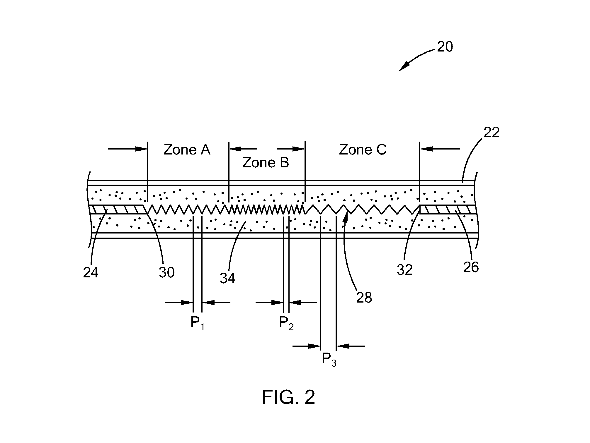
[0024]Referring to FIG. 2, a tubular heater 20 constructed in accordance with the teachings of the present disclosure includes ...


PUM


Abstract

A heater is provided that includes a resistance coil assembly defining a first end portion having a first conducting pin and a second end portion having a second conducting pin, and a resistance coil disposed between the first end portion and the second end portion, the resistance coil defining a plurality of different pitches between the first end portion and the second end portion. An insulating material surrounds the resistance coil assembly, and a sheath surrounds the insulating material. The plurality of different pitches provide a variable watt density such that a predetermined temperature profile is provided along the sheath.

Description

FIELD[0001]The present disclosure relates to electric heaters, and more specifically to electric heaters that use resistance coils to generate heat.BACKGROUND[0002]The statements in this section merely provide background information related to the present disclosure and may not constitute prior art.[0003]Tubular heaters generally include a resistance coil, an insulating material surrounding the resistance coil, and a tubular sheath surrounding the insulating material. The resistance coil is connected to a pair of conducting pins which protrude from the tubular sheath for connecting to a power source. The resistance coil generates heat, which is transferred to the tubular sheath, which in turn heats a surrounding environment or part.[0004]Tubular heaters are commonly used in heat exchangers. The heat capacity rate of the heat exchanger depends on the heat generation capability of the tubular heater, particularly, the resistance coil. To increase the heat capacity rate of the heat exc...

Claims


Application Information

Patent Timeline
IPC IPC(8): H05B3/00H05B3/44
CPCH05B3/0014H05B3/44H05B3/48H05B2203/037H05B3/52H05B2203/014F24H1/103H01C3/08H05B3/12H05B3/42H05B3/82
Inventor LONG, DENNIS P.JULIANO, ROLANDO O.
Owner WATLOW ELECTRIC MFG
Why Eureka
Try Eureka