Eureka AIR delivers breakthrough ideas for toughest innovation challenges, trusted by R&D personnel around the world.

Methods, apparatuses, assemblies, circuits and systems for assessing, estimating and/or determining relative positions, alignments, orientations and angles of rotation of a portion of a bone and between two or more portions of a bone or bones

a technology of bone and bone alignment and x-ray fluoroscopy, applied in the field of radiographic imaging, can solve the problems of narrow field, difficult to achieve the effect of large imaging area, and narrow field

Inactive Publication Date: 2013-12-05
ORTHOPEDIC NAVIGATION
View PDF4 Cites 21 Cited by
  • Summary
  • Abstract
  • Description
  • Claims
  • Application Information

AI Technical Summary

Benefits of technology

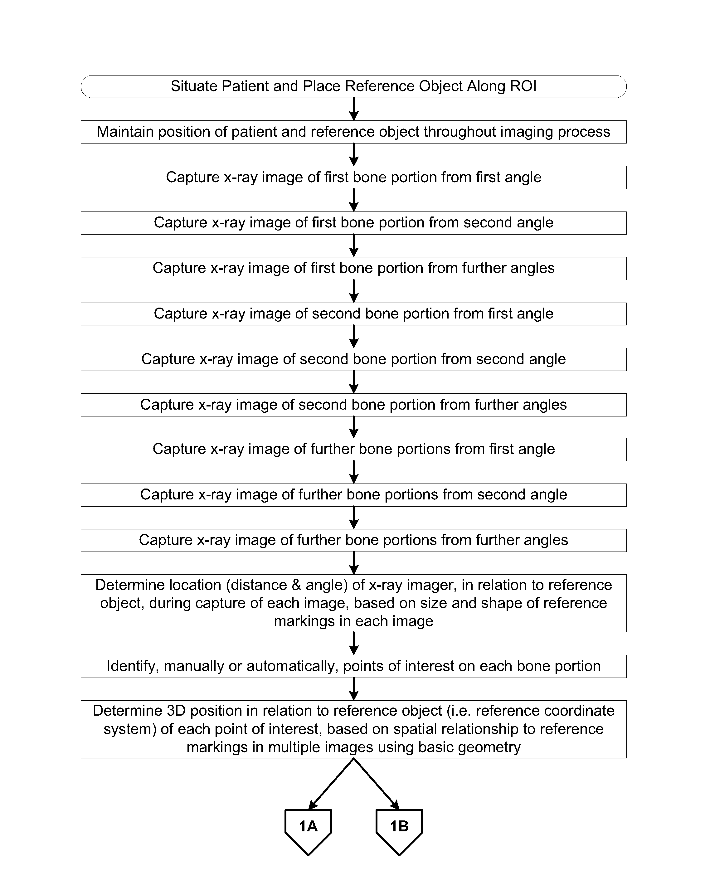
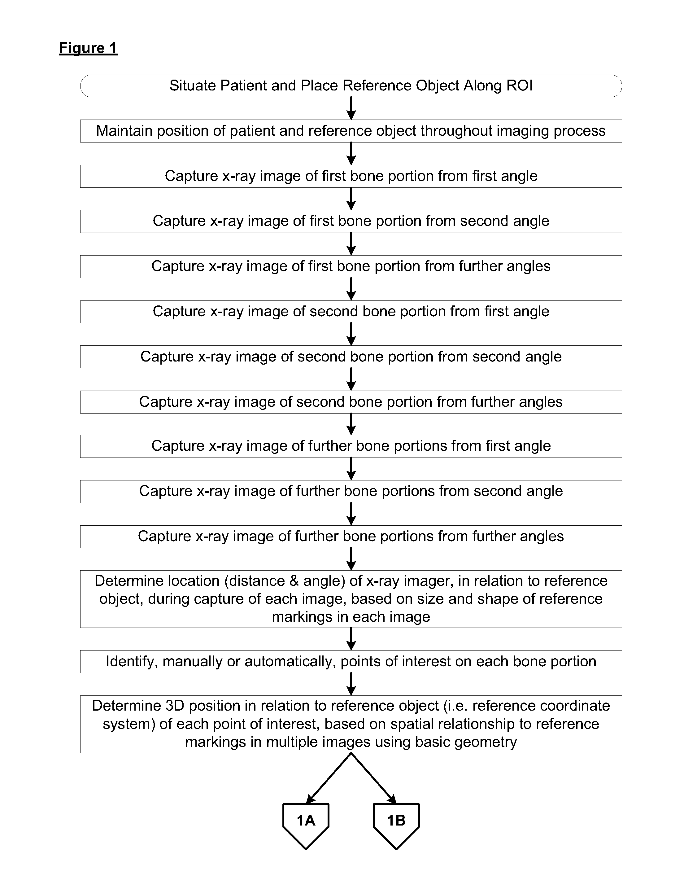
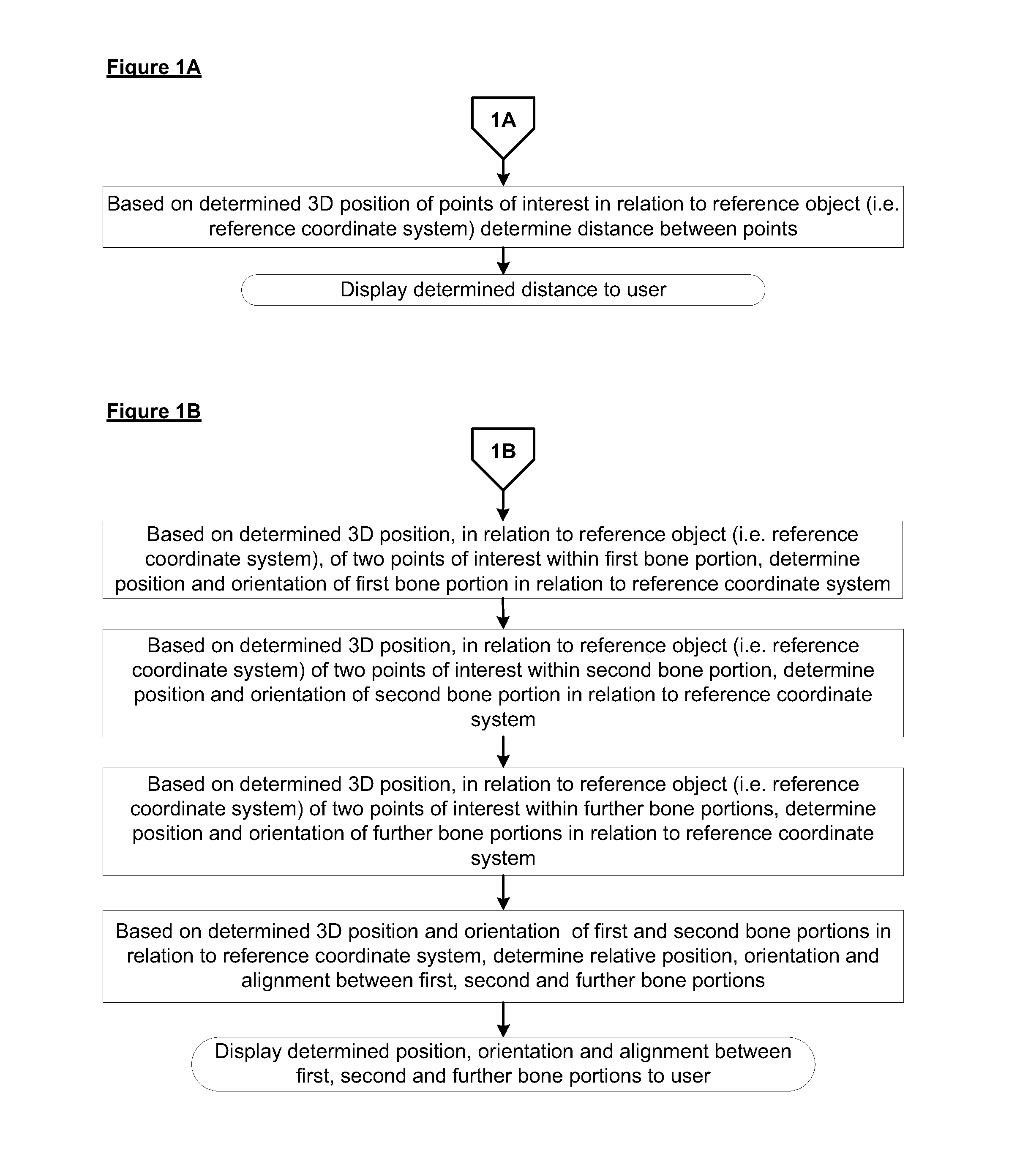
The present invention provides methods, apparatuses, circuits, and systems for assessing, estimating, and determining the relative distances, positions, orientations, and angles of rotation of a bone and between two or more portions of a bone. This is done by using a reference object, such as a grid, with identifiable shape and size elements in an image of the bone. The system analyzes images of the bone region from different angles and determines the relative position of points on the bone. The position estimates can be used to calculate the distance between points in both bone regions and to determine the alignment of the bone portions. Overall, the invention provides a reliable and precise tool for analyzing bones and assessing their fractures.

Problems solved by technology

X-ray fluoroscopy instruments have several limitations, one of which is a narrow field of view (hereinafter: “FOV”).
The narrow FOV makes imaging a large region of interest (hereinafter: “ROI”) difficult to impossible, e.g., in the case of long bones and / or implant placement.
The narrow view provided by a C-arm, however, does not provide sufficient information for a surgeon to determine relative position, distance, alignment, orientation and / or rotational angles between two or more parts of a fractured bone, such as a femur bone.

Method used


Image

  • Methods, apparatuses, assemblies, circuits and systems for assessing, estimating and/or determining relative positions, alignments, orientations and angles of rotation of a portion of a bone and between two or more portions of a bone or bones
  • Methods, apparatuses, assemblies, circuits and systems for assessing, estimating and/or determining relative positions, alignments, orientations and angles of rotation of a portion of a bone and between two or more portions of a bone or bones
  • Methods, apparatuses, assemblies, circuits and systems for assessing, estimating and/or determining relative positions, alignments, orientations and angles of rotation of a portion of a bone and between two or more portions of a bone or bones

Examples


Embodiment Construction

[0031]The following description is presented to enable any person skilled in the art to make and use the invention, and is provided in the context of particular applications of the invention and their requirements. Various modifications to the disclosed embodiments will be readily apparent to those skilled in the art and the general principles defined herein may be applied to other embodiments and applications without departing from the scope of the present invention. Thus, the present invention is not intended to be limited to the embodiments shown, but is to be accorded the widest scope consistent with the principles and features disclosed herein.

[0032]In the following detailed description, numerous specific details are set forth in order to provide a thorough understanding of the invention. However, it will be understood by those skilled in the art that the present invention may be practiced without these specific details. In other instances, well-known methods, procedures, compo...


PUM


Abstract

The present invention includes methods, apparatuses, assemblies, circuits and systems for assessing, estimating and / or determining relative distances / positions, alignment, orientation and angles of rotation of a portion of a bone and between two or more portions of a bone, e.g. a fractured bone. According to some embodiments of the present invention, there may be provided a reference object (e.g. a reference grid), which reference object may include an array of reference markings visible in a radiographic image. The reference object may be used in conjunction with one or more radiographic imaging devices and image processing circuitry to facilitate determination of a 3D position and orientation of points within images acquired by the imaging devices from different angles and spatial relationships between these points.

Description

PRIORITY CLAIM[0001]This application claims priority from:[0002]U.S. Patent Application No. 61 / 442,845, titled “Methods, Circuits, Apparatus and Systems For Assessing, Estimating and / or Determining Relative Distances, Alignment, Orientation, and Angles of Rotation Between Two or More Portions of a Bone”, filed by the inventor of the present invention on Feb. 15, 2011, which is hereby incorporated into the present description in its entirety. and[0003]U.S. Patent Application No. 61 / 487,360, titled “Method Apparatus, Assemblies, Circuits and System for Assessing Estimating and / or Determining Relative Distances Alignment Orientation and Angles of Rotation Between Two or More Portions of a Bone”, filed by the inventor of the present invention on May 18, 2011, which is hereby incorporated into the present description in its entirety.FIELD OF THE INVENTION[0004]The invention is generally related to the field of radiation based imaging. More specifically, the invention relates to methods, ...

Claims


Application Information

Patent Timeline
Patent Type & Authority Applications(United States)
IPC IPC(8): G06T7/00
CPCG06T7/0014A61B6/0407A61B6/4441A61B6/487A61B6/505A61B6/5217G06T2207/30008A61B2090/364A61B90/37G06T7/73G06T7/55G16H50/30
Inventor NATHANIEL, RAM
Owner ORTHOPEDIC NAVIGATION
Why Eureka
Eureka Blog
Learn More