
Ferrule holders with an integral lead-in tube employed in fiber optic connector assemblies, and related components, connectors, and methods

a technology of fiber optic connectors and ferrule holders, which is applied in the direction of optical elements, manufacturing tools, instruments, etc., can solve the problems of lead-in tubes that may also unexpectedly disengage from the ferrule holder, lead-in tubes may be difficult and expensive to manufacture and align, so as to achieve less expensive manufacturing and easy installation

Active Publication Date: 2013-12-05
CORNING OPTICAL COMM LLC
View PDF6 Cites 50 Cited by
  • Summary
  • Abstract
  • Description
  • Claims
  • Application Information

AI Technical Summary

Benefits of technology

This patent is about a new type of ferrule holder for fiber optic connectors that has a built-in tube to guide the optical fiber from the connector to the ferrule. This built-in tube makes the ferrule holder easier and less expensive to make, and it also helps protect the optical fiber during installation and shipment. The technical effect is that this new design helps improve the connection between optical devices.

Problems solved by technology

The lead-in tube may be difficult and expensive to manufacture and align to a ferrule holder body due to the tolerances required for use.
The lead-in tube may also unexpectedly disengage from the ferule holder because of friction with a syringe, which is temporarily inserted through the lead-in tube to inject the bonding agent before being removed.
Lead-in tubes may also unexpectedly disengage from the ferrule holder because of vibration experienced during shipping.

Method used


Image

  • Ferrule holders with an integral lead-in tube employed in fiber optic connector assemblies, and related components, connectors, and methods
  • Ferrule holders with an integral lead-in tube employed in fiber optic connector assemblies, and related components, connectors, and methods
  • Ferrule holders with an integral lead-in tube employed in fiber optic connector assemblies, and related components, connectors, and methods

Examples


Embodiment Construction

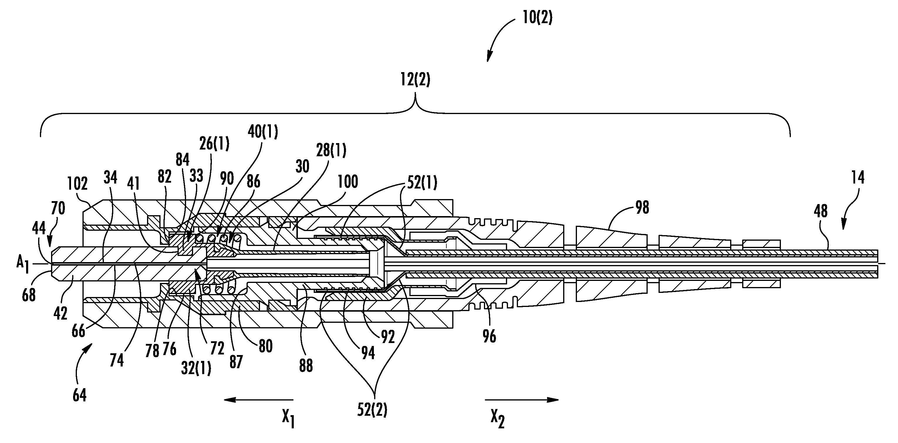
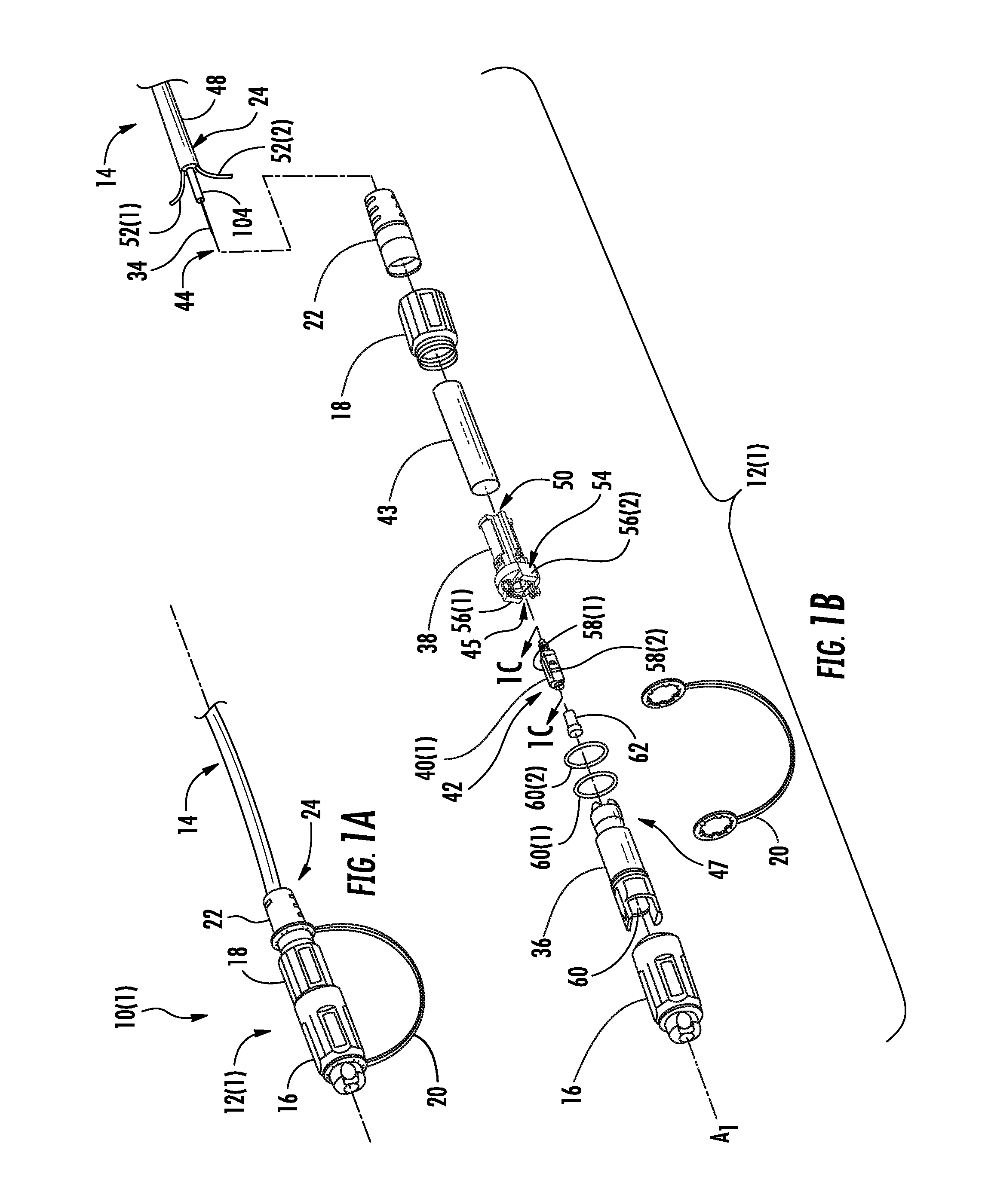
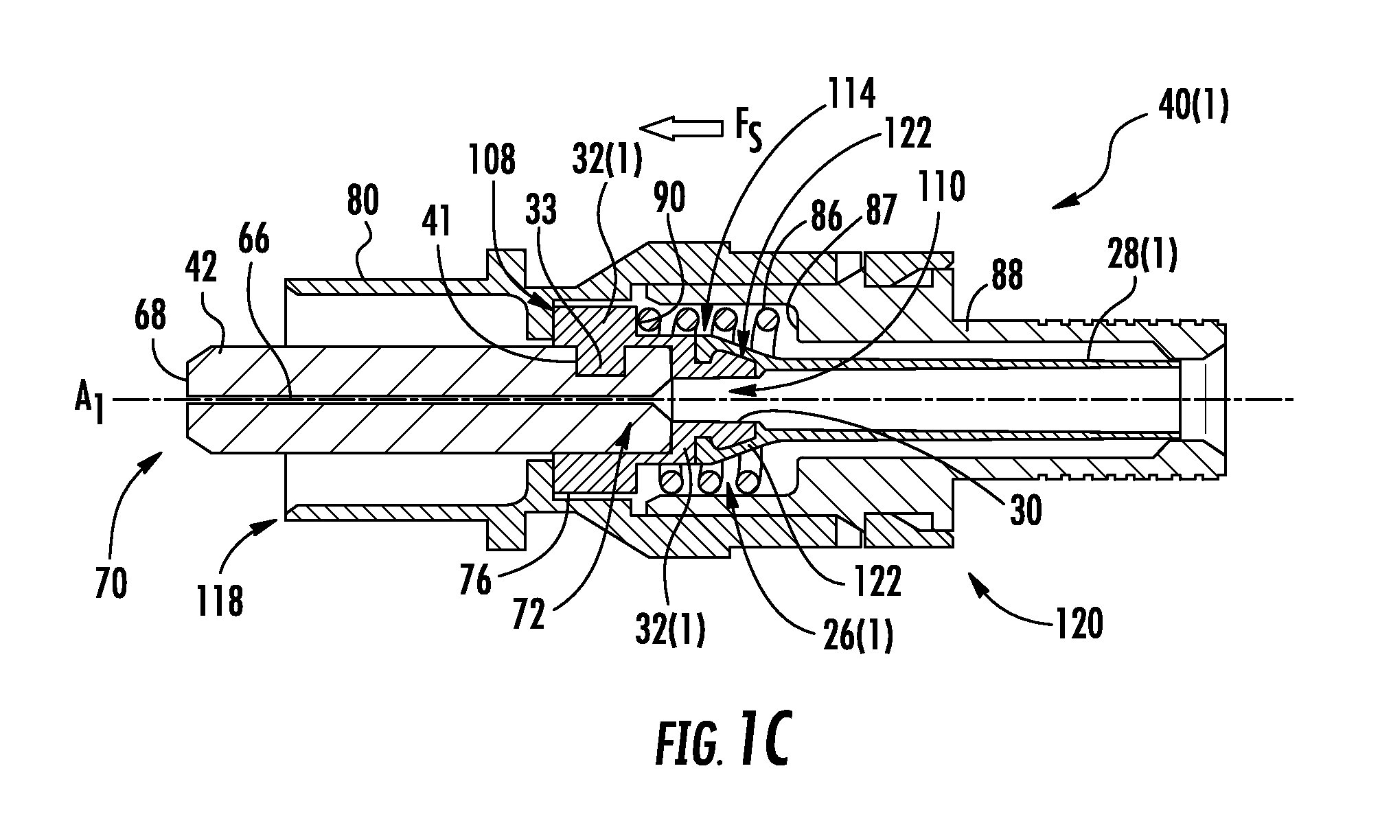
[0008]Embodiments disclosed herein include ferrule holders with an integral lead-in tube employed in fiber optic connector assemblies, and related components, connectors, and methods. By integrating the integral lead-in tube as part of the ferrule holder, the integral lead-in tube may be less expensive to manufacture and easier to install. The integral lead-in tube may also be less susceptible to inadvertent removal by friction with a bonding agent syringe or by vibration during shipment. The ferrule holder may include a ferrule holder body and integral lead-in tube. The integral lead-in tube may guide an optical fiber from a rear end of a fiber optic connector to an internal passage of the ferrule holder, where the optical fiber may be further guided to a ferrule for precise alignment with another optical device. The integral lead-in tube may also protect the optical fiber during installation, shipment, and use in the fiber optic connector.

[0009]Integrated as used herein means the ...


PUM

PropertyMeasurementUnit
widthaaaaaaaaaa
optical axisaaaaaaaaaa
spring forceaaaaaaaaaa

Abstract

Ferrule holders with an integral lead-in tube employed in fiber optic connector assemblies, and related components, connectors, and methods are disclosed. By integrating the integral lead-in tube as part of the ferrule holder, the integral lead-in tube may be less expensive to manufacture and easier to install. The integral lead-in tube may also be less susceptible to inadvertent removal by friction with a bonding agent syringe or by vibration during shipment. The ferrule holder may include a ferrule holder body and integral lead-in tube. The integral lead-in tube may guide an optical fiber from a rear end of a fiber optic connector to an internal passage of the ferrule holder, where the optical fiber may be further guided to a ferrule for precise alignment. The integral lead-in tube may also protect the optical fiber during installation, shipment, and use in the fiber optic connector.

Description

BACKGROUND[0001]1. Field of the Disclosure[0002]The technology of the disclosure relates to ferrule holders supporting ferrules in fiber optic connector assemblies for providing optic connectors for establishing fiber optic connections.[0003]2. Technical Background[0004]Optical fiber is increasingly being used for a variety of applications including but not limited to broadband voice video and data transmission. Benefits of optical fiber use include extremely wide bandwidth and low noise operation. With the increasing and varied use of optical fibers it is important to provide efficient methods of interconnecting optical fibers. Fiber optic connectors have been developed for this purpose. It is important that fiber optic connectors not significantly attenuate or alter the transmitted signal. In addition, the fiber optic connector should be relatively rugged and configured to be connected and disconnected a number of times in order to accommodate changes in the optical fiber transmis...

Claims


Application Information

Patent Timeline
Patent Type & Authority Applications(United States)
IPC IPC(8): G02B6/36B23P11/00
CPCG02B6/3825G02B6/3851G02B6/3865G02B6/3869Y10T29/49826G02B6/3834
Inventor HENKE, CHARLES T.PARKMAN, III, LOUIS E.
Owner CORNING OPTICAL COMM LLC
Learn More