Apparatus for minimizing solid particle erosion in steam turbines

a technology of steam turbines and minimizing solid particle erosion, which is applied in mechanical apparatus, machines/engines, liquid fuel engines, etc., can solve the problems of reducing steam turbine performance and mechanical reliability, affecting the performance of steam turbines, and the opportunity to inflict considerable damage along the steam path

Active Publication Date: 2013-12-05
GENERAL ELECTRIC CO
View PDF5 Cites 3 Cited by
  • Summary
  • Abstract
  • Description
  • Claims
  • Application Information

AI Technical Summary

Problems solved by technology

As they pass through the steam turbine, the particles cause damage to both the stationary and rotating parts of the turbine which degrades steam turbine performance and mechanical reliability.
However, since the particles are transported by the main steam flow through the steam turbine steam path, they have the opportunity to inflict considerable damage along the steam path before they are deposited or expelled from the main steam flow.
This damage can include erosion of the rotating and stationary buckets and partitions respectively, erosion of the rotating tip covers or tenons, erosion of tip sealing devices such as spill strips and erosion of stationary structures over the tips of the rotating buckets.
One drawback associated with this arrangement is that the particles do not easily enter the inlet opening 64.
In other words, the shape of the diaphragm surface adjacent the inlet opening does not effectively direct particles to the inlet opening.
Thus, particles forced near the inlet opening by centrifugal action are often still deposited under the covers of the rotating buckets, which degrades mechanical integrity of the rotating buckets.
Further, even when particles successfully enter the inlet opening 64, they are not easily passed through the hole 60.
While many of these and other efforts to minimize or eliminate solid particle erosion have been tried in the past, solid particle erosion in steam turbines remains a continuing problem for the various parts along the steam path.

Method used


Image

  • Apparatus for minimizing solid particle erosion in steam turbines
  • Apparatus for minimizing solid particle erosion in steam turbines
  • Apparatus for minimizing solid particle erosion in steam turbines

Examples


Embodiment Construction

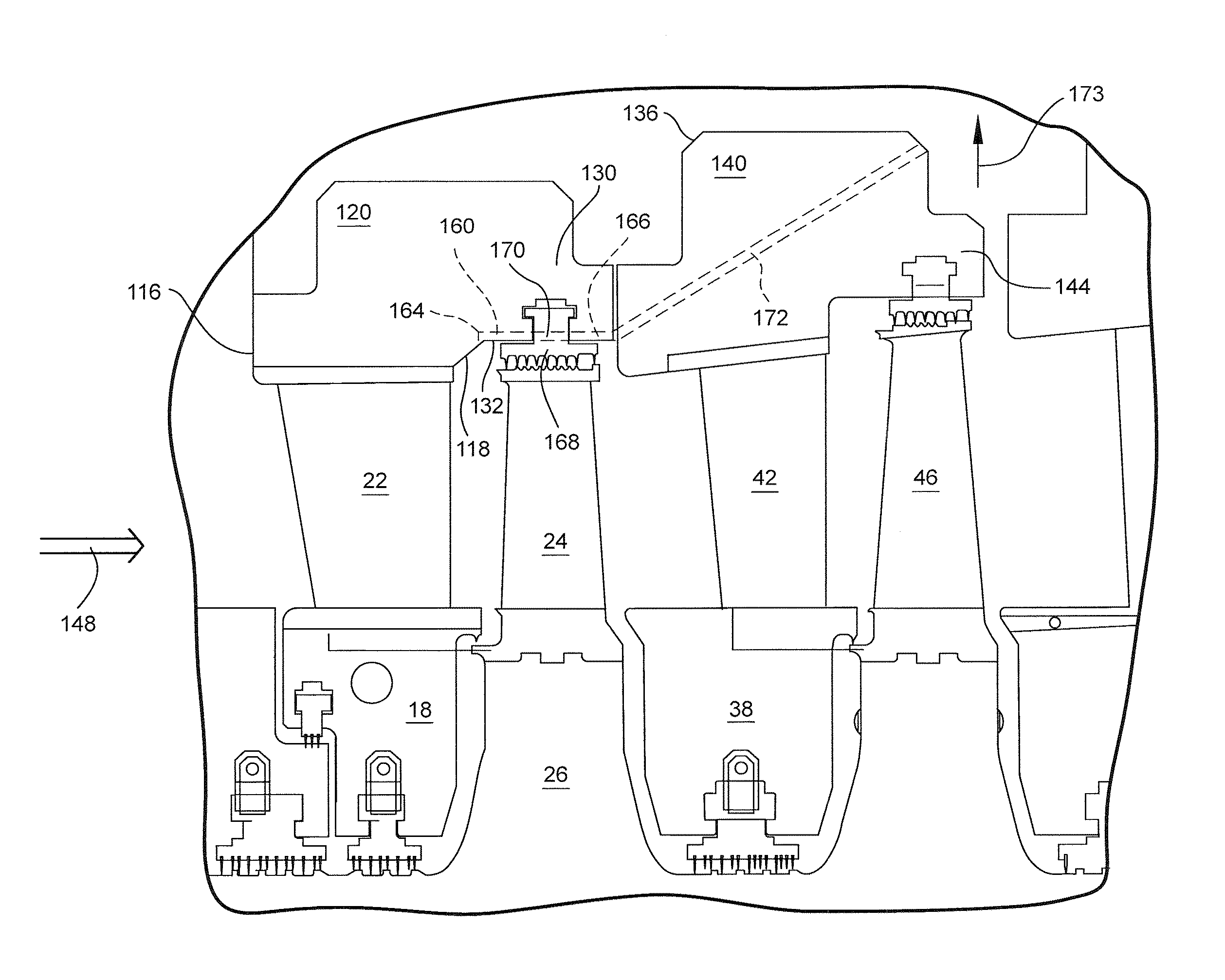
[0021]Referring to FIG. 4, and as noted previously, solid particles flowing in the steam path tend to erode the various components of the turbine causing degradation in performance and efficiency. The region denoted O in. FIG. 4 constitutes the trailing edge of the partitions. Solid particle erosion in region O can seriously affect the mechanical integrity of the stationary vanes, potentially impact the mechanical integrity of the rotating vanes due to forced response phenomena and degrade stage performance due to the increase in stationary vane area, throat shape and flow angle degradation. Region {circle around (2)} in FIG. 4 denotes an area of increased tip leakage of steam due to solid particle erosion to the tip sealing devices, e.g., devices 28. Region 3 in FIG. 4 denotes areas where solid particles are deposited by centrifugal action under the covers of the rotating buckets. Such deposits can degrade mechanical integrity of the rotating buckets by changing the response of the...


PUM


Abstract

Solid particle erosion in a steam turbine is minimized by diverting through angled slots formed in appendages of outer rings of the diaphragms, a portion of the steam from the steam flow path thereby bypassing downstream rotating components. The slot through the first stage appendage lies in communication with a passage through a downstream outer ring of a following stage such that the diverted solid particle containing steam may be extracted from the steam flow path and passed to the feed water heater of the turbine. The slot in the second stage appendage diverts steam from between the first and second stages and about the second stage. Solid particle erosion in various regions, i.e., the trailing edge of the stator vanes, along the surfaces of the buckets and in the regions of the cover and its connection with the buckets as well as the sealing devices is thereby minimized.

Description

FIELD OF THE INVENTION[0001]The present invention relates to an apparatus for minimizing solid particle erosion in steam turbine components, and particularly relates to an apparatus for removing solid particles from the steam flow path to minimize damage to, for example, turbine buckets.BACKGROUND OF THE INVENTION[0002]Solid particle erosion of the components of a steam turbine occurs due to carryover of particles from the steam boiler and piping upstream of the turbine. The solid particles become entrained in the steam flow path. As they pass through the steam turbine, the particles cause damage to both the stationary and rotating parts of the turbine which degrades steam turbine performance and mechanical reliability. The solid particles may be deposited throughout the steam path or may exit the steam path into steam extractions that feed the feed water heaters of the cycle. However, since the particles are transported by the main steam flow through the steam turbine steam path, t...

Claims


Application Information

Patent Timeline
Patent Type & Authority Applications(United States)
IPC IPC(8): F01D5/14F01D5/02
CPCF01D25/32F05D2220/31
Inventor MITCHELL, DOUGLAS ROBERT
Owner GENERAL ELECTRIC CO
Why Eureka
Try Eureka