Torque limiter, variable transmission ratio device, and tolerance ring

a technology of variable transmission ratio and tolerance ring, which is applied in the direction of slipping coupling, coupling, gearing, etc., can solve the problems of variable transmission ratio device and excessive slipping torqu

Inactive Publication Date: 2013-12-05
JTEKT CORP +2
View PDF12 Cites 16 Cited by
  • Summary
  • Abstract
  • Description
  • Claims
  • Application Information

AI Technical Summary

Benefits of technology

[0010]An object of the present invention is to provide a torque limiter, a variable transmission ratio device, and a tolerance ring which can suppress a decrease in a slipping torque due to an impact.

Problems solved by technology

However, in this case, in a state where the shaft center of the motor shaft 82 and the shaft center of the lock holder 83 match each other, the slipping torque becomes excessively large.
The above-described problem occurs not only in a variable transmission ratio device but also in a torque limiter including a shaft-shaped first rotating member, a second rotating member that is fitted on the first rotating member, and a tolerance ring disposed between the first and second rotating members when an impact is applied to the second rotating member.

Method used


Image

  • Torque limiter, variable transmission ratio device, and tolerance ring
  • Torque limiter, variable transmission ratio device, and tolerance ring
  • Torque limiter, variable transmission ratio device, and tolerance ring

Examples


first embodiment

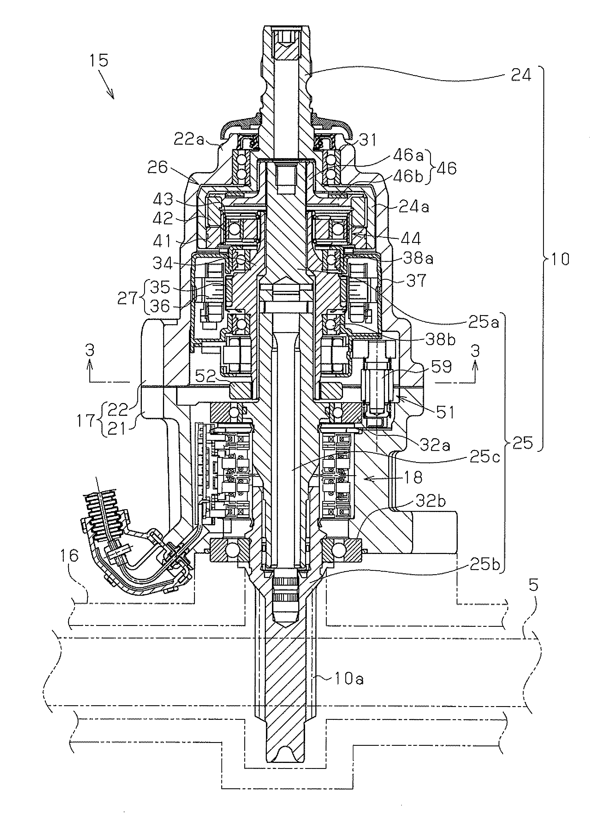
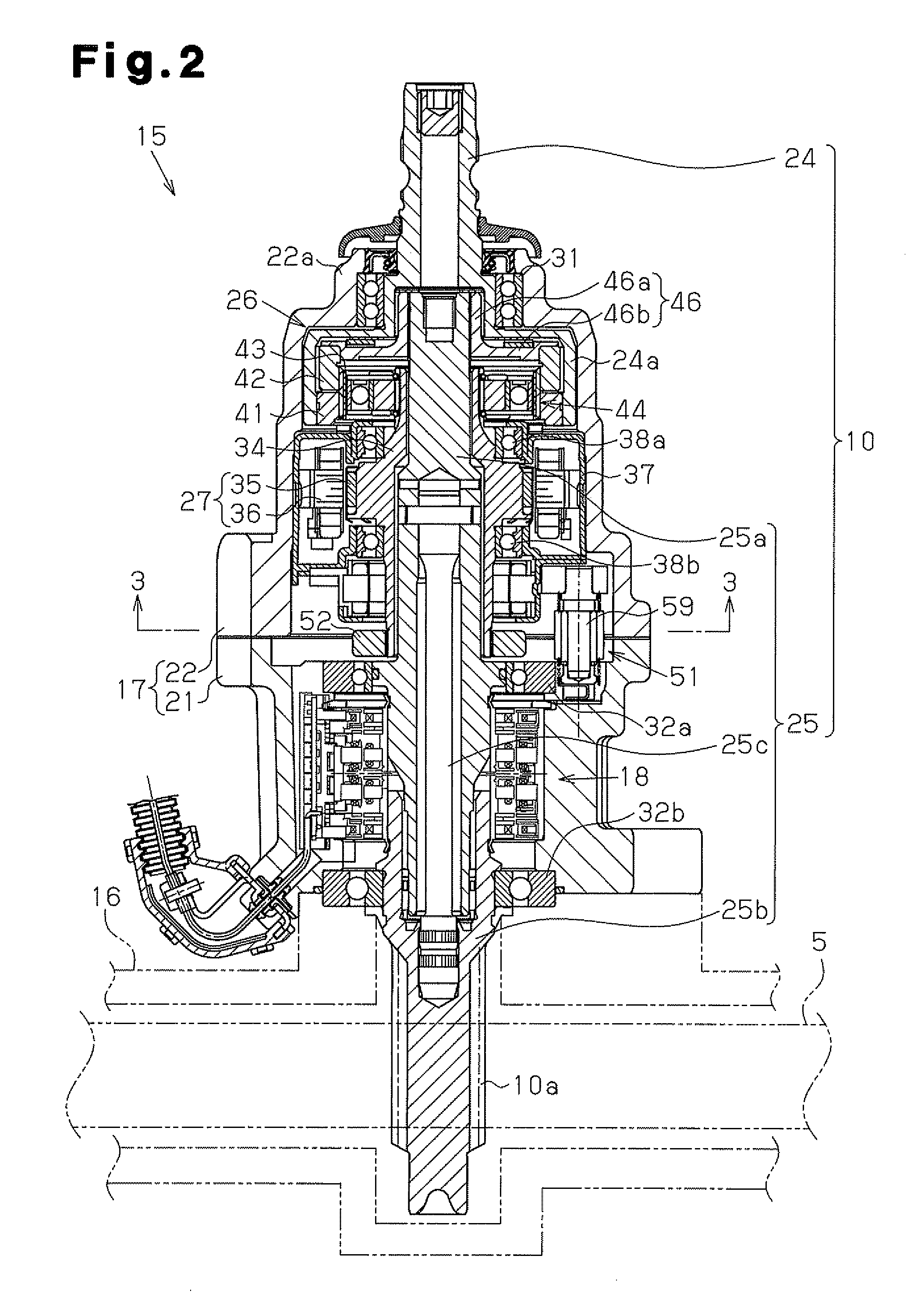
[0041]Hereinafter, a first embodiment that embodies the present invention is described with reference to FIG. 1 to FIG. 5. The present invention is described by defining the upper side and the lower side as shown in FIG. 2.

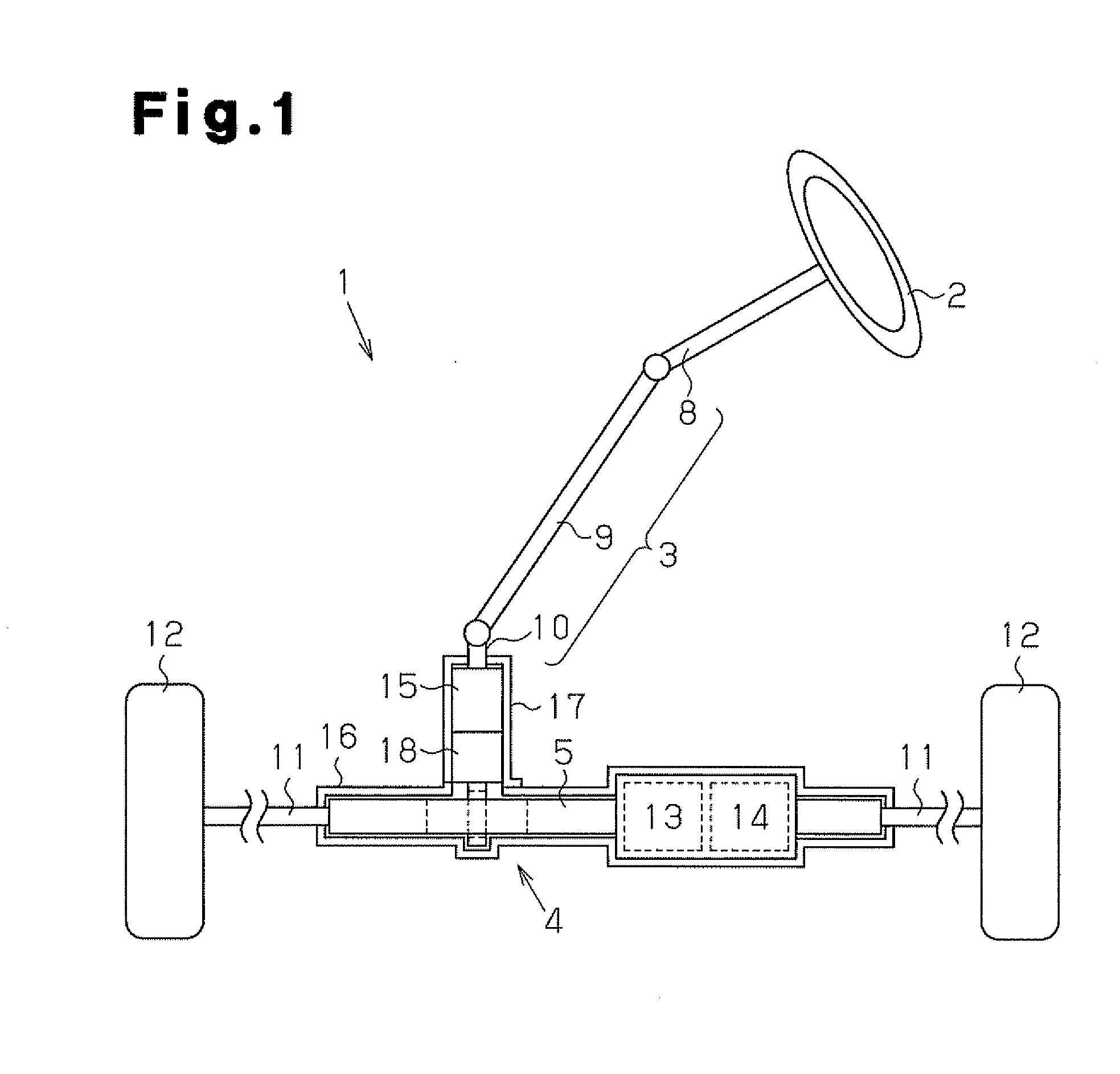
[0042]As shown in FIG. 1, in a vehicle steering apparatus 1, a steering wheel 2 is fixed to a steering shaft 3. The steering shaft 3 is joined to a rack shaft 5 by a rack-and-pinion mechanism 4. Rotation of the steering shaft 3 according to a steering operation is converted into reciprocating linear movement of the rack shaft 5 by the rack-and-pinion mechanism 4. In the steering shaft 3, a column shaft 8, an intermediate shaft 9, and a pinion shaft 10 are joined to each other. To both ends of the rack shaft 5, tie rods 11 are joined, respectively. Reciprocating linear movement of the rack shaft 5 according to rotation of the steering shaft 3 is transmitted to knuckles (not illustrated) via the tie rods 11. Accordingly, the turning angle of steered wheels 12, that ...

second embodiment

[0070]Next, a second embodiment that embodies the present invention is described with reference to FIG. 6(a) to FIG. 6(c). The same configurations as in the first embodiment are provided with the same reference symbols, and description thereof is omitted.

[0071]As shown in FIG. 6(a) to FIG. 6(c), the main protrusion 71 is respectively formed near each of open ends of the ring main body 65. The main protrusions 71 are disposed at a predetermined interval in the axial direction of the ring main body 65.

[0072]The second embodiment provides the following effects in addition to the effects of (1) and (2) described above.

[0073](3) An impact is applied to the lock holder 52 and the axis of the lock holder 52 may be tilted with respect to the axis of the motor shaft 34. In this case, the contact states between the main protrusions 71, sub-protrusions 72 and the lock holder 52 become uneven, and frictional resistance between the protrusions 71 and 72 and the lock holder 52 may be reduced. In ...

third embodiment

[0074]Next, a third embodiment that embodies the present invention is described with reference to FIG. 7(a) to FIG. 7(c). The same configurations as in the first embodiment are provided with the same reference symbols, and description thereof is omitted.

[0075]As shown in FIG. 7(a) to FIG. 7(c), the main protrusion 71 is respectively formed near each of both open ends of the ring main body 65. The main protrusions 71 are disposed at a predetermined interval in the axial direction of the ring main body 65. The sub-protrusions 72 are formed substantially into trapezoidal quadrangular pyramids. The sub-protrusion 72 extends from the vicinity of one open end to the vicinity of the other open end of the ring main body 65. The apex of the main protrusion 71 extends along the axis. The sectional shape of the main protrusion 71 orthogonal to the axis is substantially triangular. The main protrusions 71 and the sub-protrusions 72 are formed by plastically deforming the ring main body 65 by me...


PUM


Abstract

This torque limiter is configured from a ring body and a spring-form part provided in the ring body. The ring body comprises a band-form metal plate and is bent approximately into a C-shape along the circumferential direction of a motor shaft and a lock holder. The spring-form part is formed so as to be capable of radial elastic deformation. The spring-form part is configured from main protrusions arranged in a compressed state between the motor shaft and the lock holder, and from sub-protrusions arranged in a non-compressed state. Further, grease is stored in a part or all of the concavities formed by the main protrusions and the sub-protrusions.

Description

TECHNICAL FIELD[0001]The present invention relates to a torque limiter, a variable transmission ratio device, and a tolerance ring.BACKGROUND ART[0002]Conventionally, a variable transmission ratio device which uses a differential mechanism and adds rotation based on motor driving to rotation of an input shaft based on a steering operation and transmits the added rotations to an output shaft is known. Patent Document 1 discloses a housing-fixed type variable transmission ratio device in which a housing for housing a differential mechanism and a motor is fixed to a vehicle body of a motor vehicle. The variable transmission ratio device disclosed in this document includes a locking device. The locking device suppresses idling of a motor shaft when power supply to the motor is stopped, and restrains rotation of the motor shaft to enable torque transmission between the input shaft and the output shaft.[0003]As shown in FIG. 9, a locking device 81 described in Patent Document 1 includes a...

Claims


Application Information

Patent Timeline
Patent Type & Authority Applications(United States)
IPC IPC(8): F16D7/02
CPCF16D7/025B62D5/008F16D1/0835F16D7/021
Inventor ASAKURA, TOSHIHIROFUJIMOTO, MASATOSHIOGATA, TOSHIAKIKANAYAMA, YUKIHIKOSUZUKI, HIROTSUNENAKAMURA, YUJIHIRAKAWA, YUZOHAYASHI, KENJITOYODA, HIROYUKI
Owner JTEKT CORP
Why Eureka
Try Eureka