Roof Pipe Flashing

a technology for roof pipes and flashing, applied in snow traps, building repairs, transportation and packaging, etc., can solve problems such as water leakage and subsequent damage to roof structures, and achieve the effect of saving tim

Inactive Publication Date: 2013-12-12
BOND WILLIAM RALPH
View PDF10 Cites 29 Cited by
  • Summary
  • Abstract
  • Description
  • Claims
  • Application Information

AI Technical Summary

Benefits of technology

[0005]The purpose of this invention is to provide a water tight cover for an existing but damaged roof pipe flashing without removing the damaged roof pipe flashing and to accomplish this in an expeditious way saving time and without removal of the damaged roof pipe flashing from the roof of a building. In order to accomplish this, a modified roof pipe flashing is used to cover the damaged boot of an existing roof pipe flashing. The roof pipe flashing of this invention includes a boot generally about the same size as the boot of an existing but dama...

Problems solved by technology

A problem which can occur over time with vent pipes extending through the roof of a building is deteriorization of th...

Method used


Image

  • Roof Pipe Flashing
  • Roof Pipe Flashing
  • Roof Pipe Flashing

Examples


Embodiment Construction

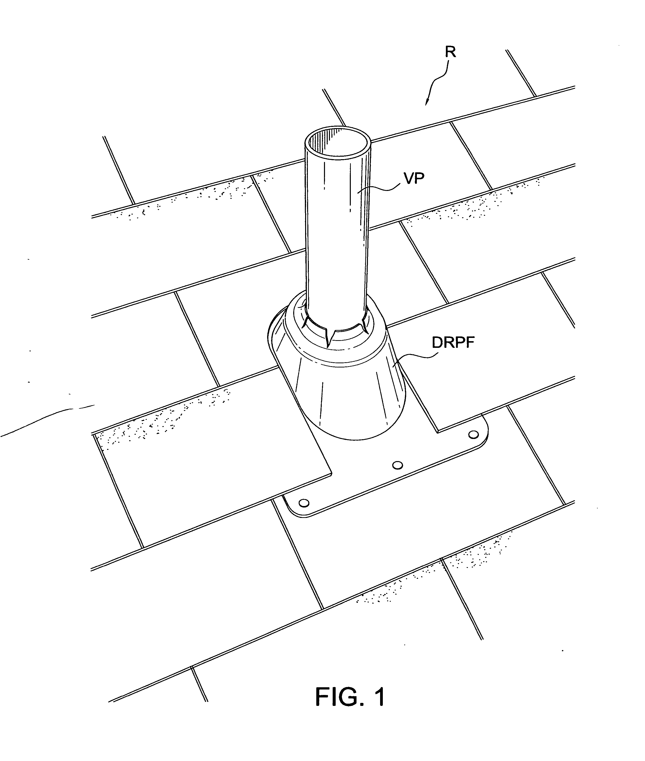
[0019]FIG. 1 shows a damaged boot of an existing roof pipe flashing (DRPF) for a vent pipe VP which would result in water leakage and probable damage to the roof R of a building. This is the type of damage that the roof pipe flashing of this invention intends to repair.

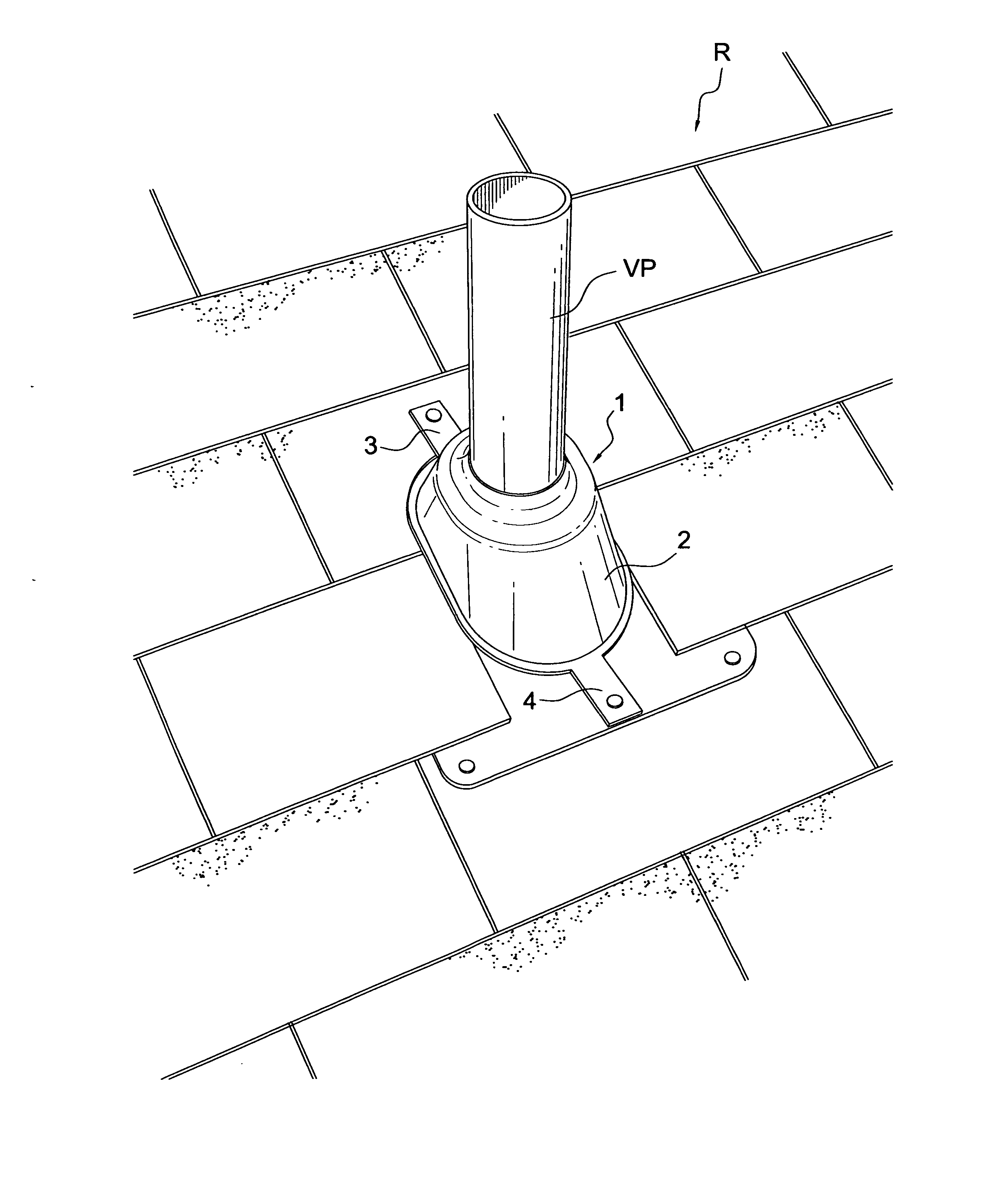
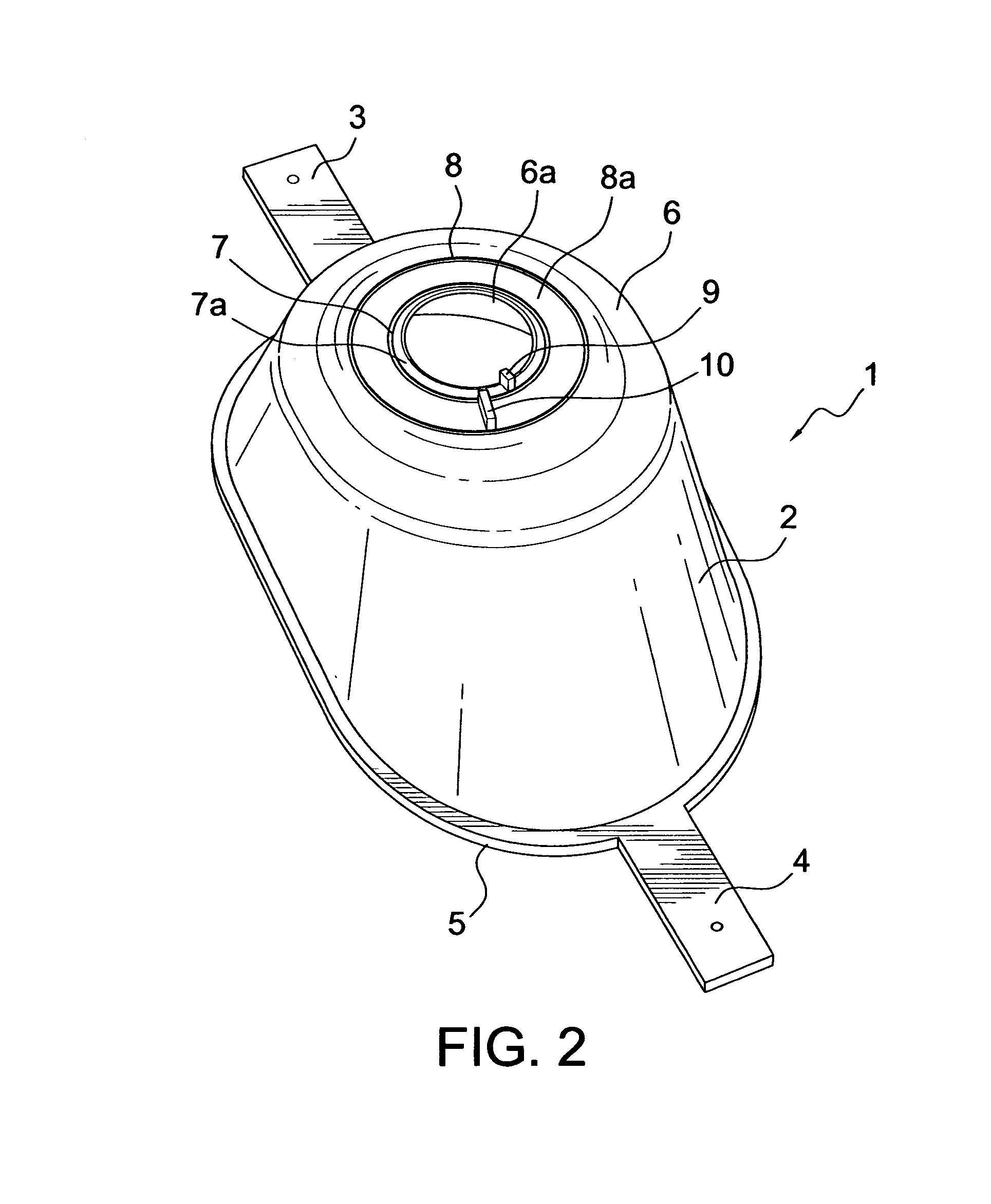
[0020]Referring to FIG.2, there is shown the roof pipe flashing 1 of this invention. The roof pipe flashing 1 includes a raised boot 2 and two extensions 3 and 4 extending from opposite sides at the bottom end 5 of the raised boot 2. The extensions 3 and 4 are used to anchor the raised boot to the roof R of the building. The extensions 3 and 4 preferably extend from about three inches from the bottom end 5 of the raised boot 2 but can vary somewhat longer or shorter. The width of each extension is approximately two inches but can vary somewhat wider or narrower. The raised boot 2 is somewhat frusto-conical in shape and has an opening 6a at the top end 6 thereof to accommodate a vent pipe VP extending therethrough. The...


PUM

PropertyMeasurementUnit
Diameteraaaaaaaaaa
Widthaaaaaaaaaa

Abstract

A roof pipe flashing with a raised boot and elongated opposite extensions extending therefrom which roof pipe flashing is used to cover and weatherproof an existing but damaged roof pipe flashing on the pitched roof of a building. The roof pipe flashing can be made manually by cutting or tearing along pre-marked lines on the flat base of a roof pipe flashing.

Description

BACKGROUND OF THE INVENTION[0001]1. Field of the Invention[0002]The present invention relates to a roof pipe flashing and particularly the repair of a damaged roof pipe flashing.[0003]2. Description of the Related Art[0004]A problem which can occur over time with vent pipes extending through the roof of a building is deteriorization of the flashing boot surrounding the vent pipe causing water leakage therethrough and subsequent damage to the roofing structure. Several prior art methods have been used to repair existing roof pipe flashings by covering the boot of the existing roof pipe flashing with a similar shaped boot over the existing boot in order to prevent water leakage. One such method is disclosed in the publication US 2001 / 0219723 where a vent pipe cover comprising a cylindrical sheath portion joined to a flaring boot portion is used. The cylindrical sheath portion is slid over the cylindrical vent pipe and the flaring boot portion is placed over an existing roof boot. The ...

Claims


Application Information

Patent Timeline
IPC IPC(8): E04D13/14B26F3/02B26D3/00
CPCB26D3/00B26F3/02E04D13/1476Y10T83/04Y10T225/10
Inventor BOND, WILLIAM RALPH
Owner BOND WILLIAM RALPH
Why Eureka
Try Eureka