Video sender and video receiver

a video sender and video receiver technology, applied in the field of video sender and video receiver, can solve the problem that the receiver cannot make a setting

Active Publication Date: 2013-12-12
HISENSE VISUAL TECH CO LTD
View PDF15 Cites 13 Cited by
  • Summary
  • Abstract
  • Description
  • Claims
  • Application Information

AI Technical Summary

Problems solved by technology

However, in the conventional technology, when the video sender cannot transmit all color signals for all frames of the video that can be output to the video receiver b...

Method used


Image

  • Video sender and video receiver
  • Video sender and video receiver
  • Video sender and video receiver

Examples


Embodiment Construction

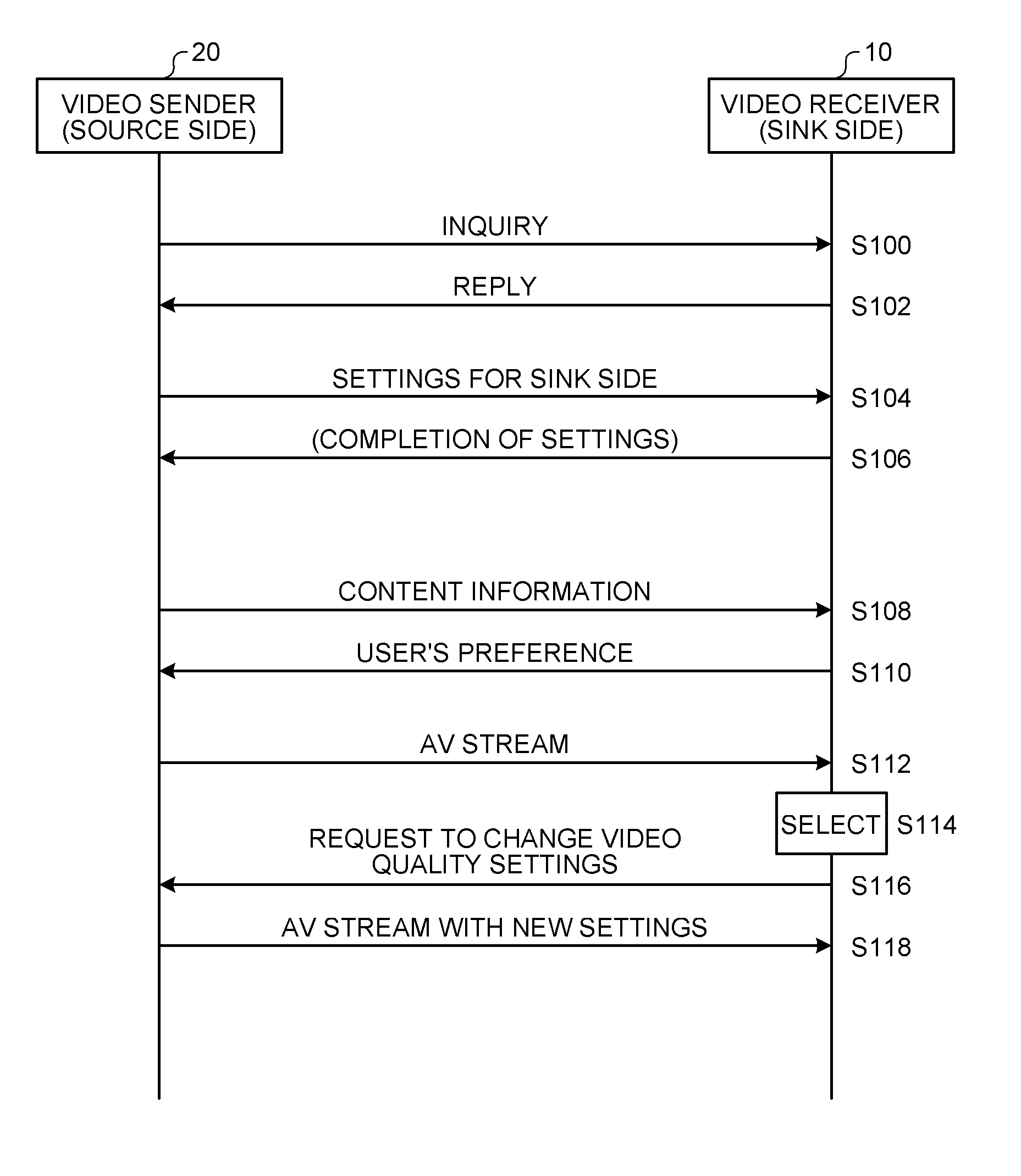
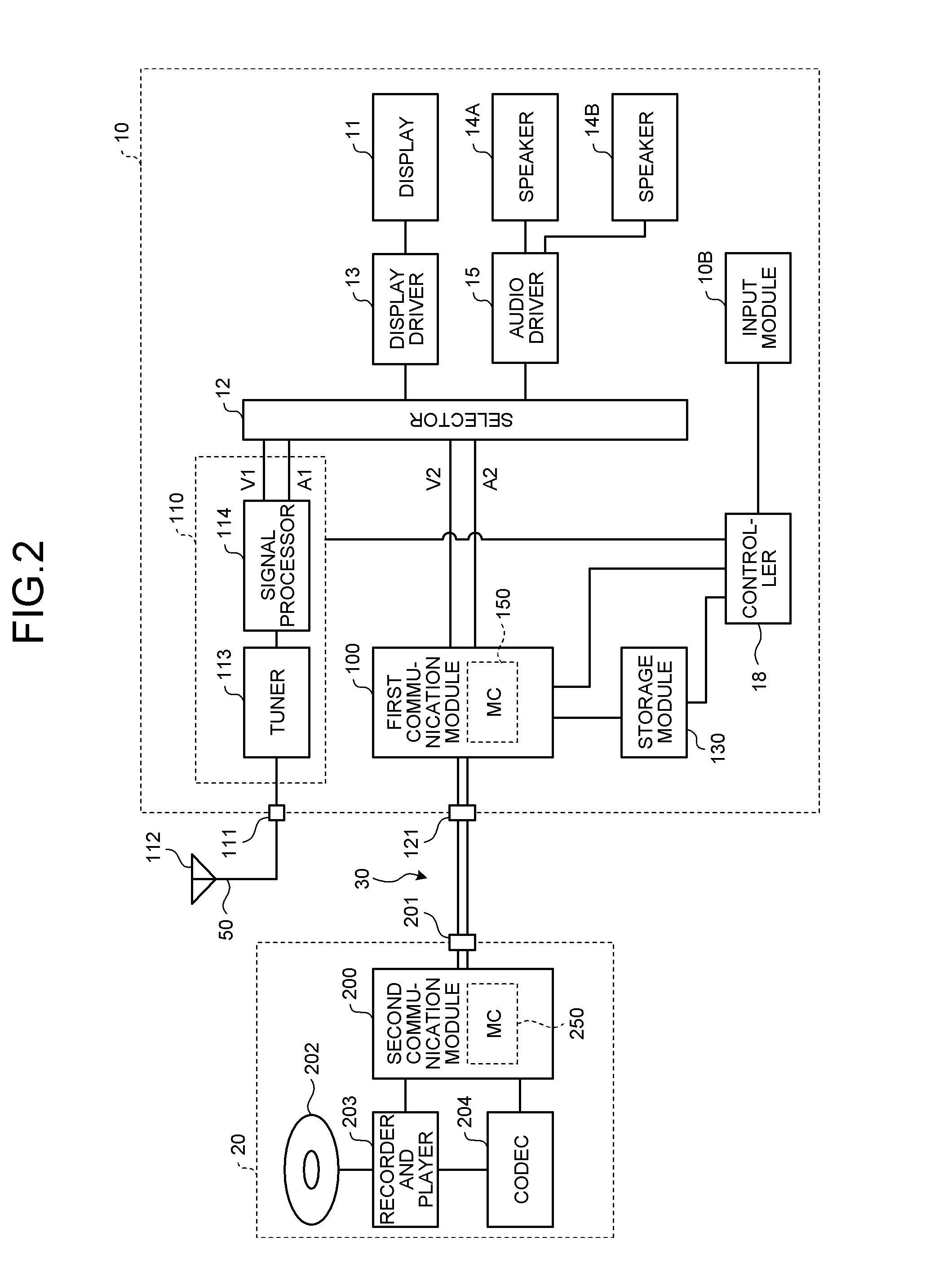
[0017]In general, according to one embodiment, a video sender comprises: a video processor configured to create video; and a communication module configured to communicate with a video receiver. The communication module comprises: a receiver; and a transmitter. The receiver is configured to receive, from the video receiver, specific information specifying which one of a color signal and a frame rate takes precedence over the other one in transmission. The transmitter is configured to convert the video created by the video processor into video in which one of the color signal and the frame rate takes precedence over the other one in accordance with the specific information, and transmit the video thus converted to the video receiver.

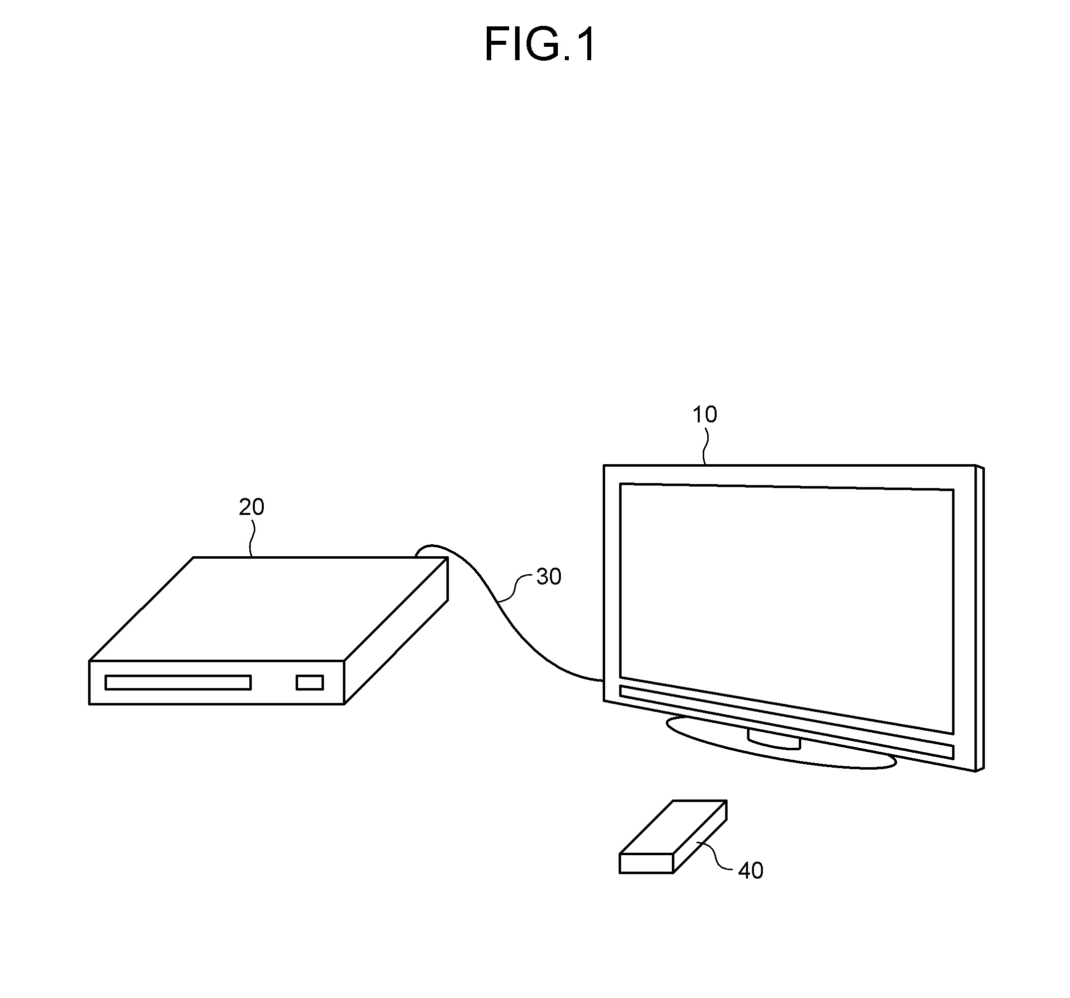
[0018]With reference to the accompanying drawings, embodiments of the video receiver and the video sender will now be described in detail. FIG. 1 is an external view illustrating an example of a coupling between a video receiver 10 and a video sender 20 i...


PUM


Abstract

According to one embodiment, a video sender comprises: a video processor and a communication module. The video processor creates video. The communication module is configured to communicate with a video receiver. The communication module comprises: a receiver and a transmitter. The receiver receives, from the video receiver, specific information specifying which one of a color signal and a frame rate takes precedence over the other one in transmission. The transmitter converts the video created by the video processor into video in which one of the color signal and the frame rate takes precedence over the other one in accordance with the specific information, and transmit the video thus converted to the video receiver.

Description

CROSS-REFERENCE TO RELATED APPLICATIONS[0001]This application is based upon and claims the benefit of priority from Japanese Patent Application No. 2012-131472, filed Jun. 11, 2012, the entire contents of which are incorporated herein by reference.FIELD[0002]Embodiments described herein relate generally to a video sender and a video receiver.BACKGROUND[0003]High-Definition Multimedia Interface (HDMI) is an example of multimedia interfaces between a video sender such as a Blu-ray (registered trademark) disc (BD) player, a digital versatile disc (DVD) player, and a set-top box, and a video receiver such as a television set and a monitor. A device with an HDMI output port is referred to as a source device, while a device with an HDMI input port is referred to as a sink device. The video sender is a source device, while the video receiver is a sink device.[0004]In HDMI communication equipment that performs communication compliant to the HDMI standards comprises a transition minimized di...

Claims


Application Information

Patent Timeline
IPC IPC(8): H04N9/64
CPCH04N9/64G09G5/006H04N21/4325H04N21/43635H04N21/440263H04N21/440281H04N21/4621H04N21/485G09G2340/0407G09G2340/0428G09G2340/0435G09G2320/08G09G2320/0613G09G5/36G09G5/003G09G2350/00G09G2370/045G09G2370/12G09G2370/06H04N1/00095H04N1/00114H04N5/04H04N5/38H04N5/44H04N21/440272H04N21/4755H04N21/4854
Inventor MINEMURA, TAKASHISUZUKI, NOBUAKIDOI, TAKASHIMIYASATO, HIDEKI
Owner HISENSE VISUAL TECH CO LTD
Why Eureka
Try Eureka