Fluidization and alignment elbow

a technology of elbows and elbows, applied in the direction of conveyors, conveyors, transportation and packaging, etc., can solve the problems of inability to design straight lines from one point to another, belt conveyors would not be desired in certain cases, etc., and achieve the effect of facilitating the downward movement of solid particles

Inactive Publication Date: 2013-12-12
BABCOCK POWER SERVICES
View PDF20 Cites 3 Cited by
  • Summary
  • Abstract
  • Description
  • Claims
  • Application Information

AI Technical Summary

Benefits of technology

[0007]The subject invention is directed to a new and useful elbow for a solid particle conveyance system. The elbow includes an elbow body having an inlet duct and an outlet duct with an interior space defined between the inlet and outlet ducts. An aeration insert is mounted to the elbow body for aerating solid particles passing through the interior space of the elbow body. The aeration insert is mounted to the elbow body to provide aeration from an elevation between that of the inlet duct and the outlet duct to facilitate downward movement of solid particles from the inlet duct across the aeration insert, and out through the outlet duct.

Problems solved by technology

A belt conveyor would not be desired in certain cases due to the density of material, corrosive nature, or temperature of material desired to be transferred.
In a fluidization conveyor system, straight line runs from one point to another are not always possible to design due to pre-existing mechanical structures or the like.

Method used


Image

  • Fluidization and alignment elbow
  • Fluidization and alignment elbow
  • Fluidization and alignment elbow

Examples


Embodiment Construction

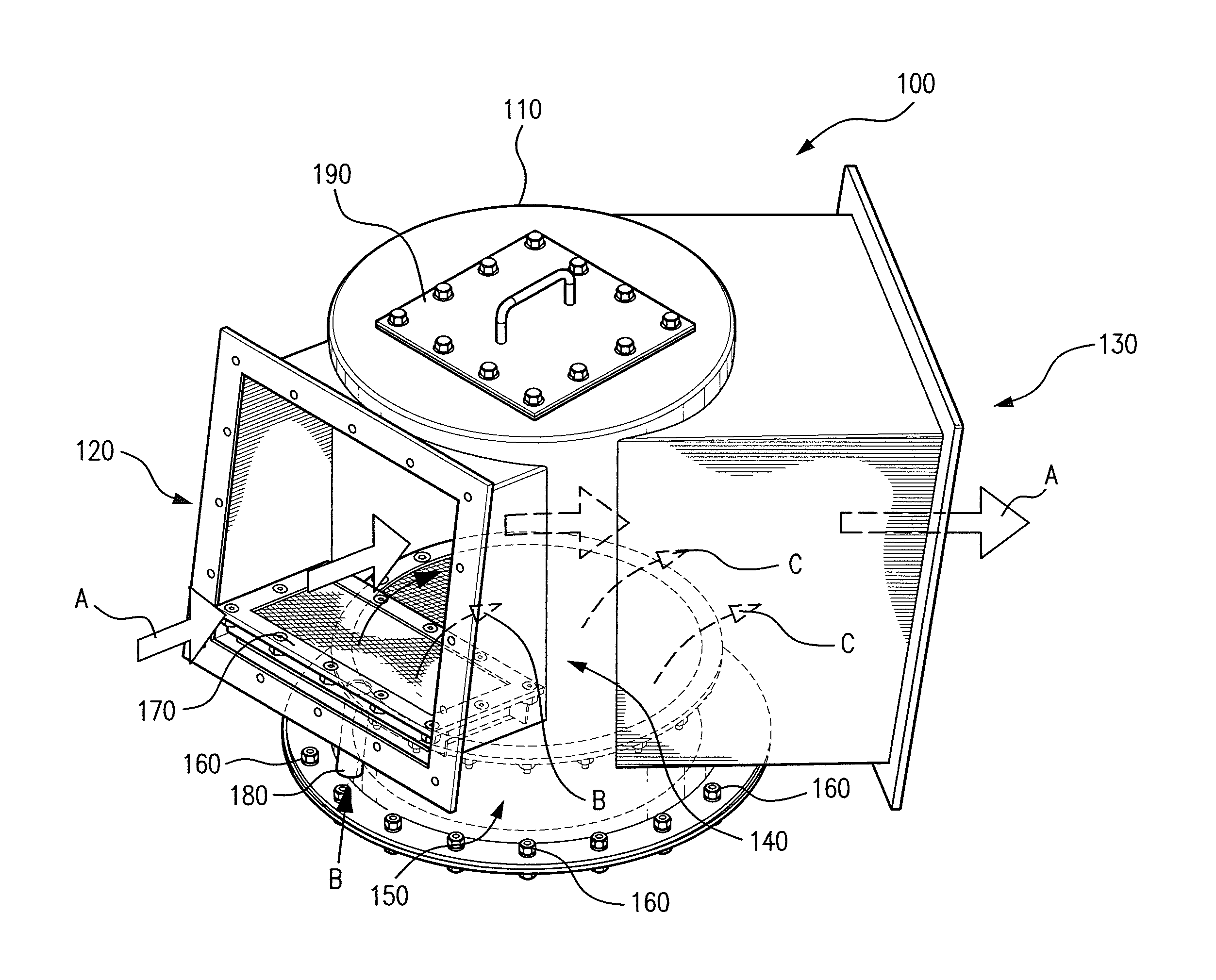
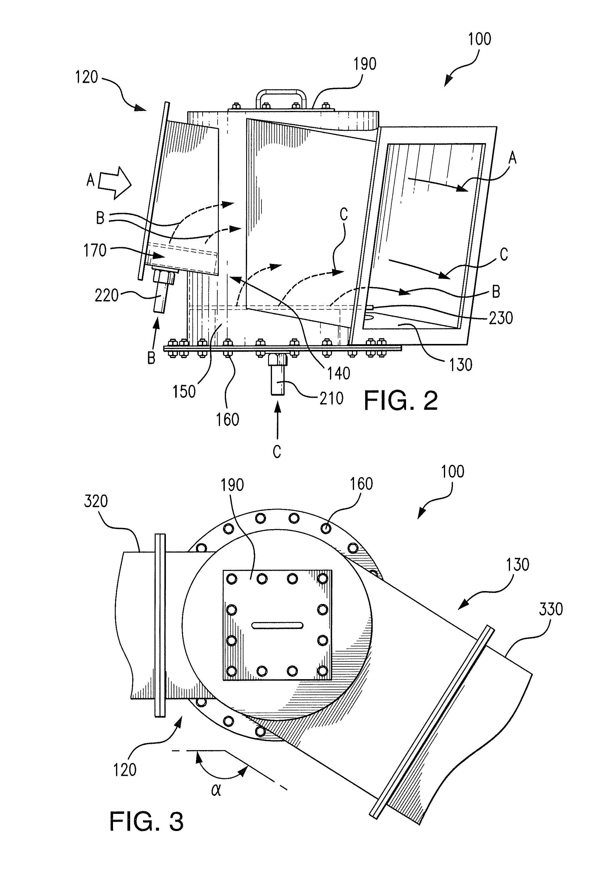
[0017]Reference will now be made to the drawings wherein like reference numerals identify similar structural features or aspects of the subject invention. For purposes of explanation and illustration, and not limitation, a partial view of an exemplary embodiment of an elbow for a solid particle conveyance system in accordance with the invention is shown in FIG. 1 and is designated generally by reference character 100. Other embodiments of elbows in accordance with the invention, or aspects thereof, are provided in FIGS. 2-4, as will be described. The system of the invention can be used to transport aerated solid particles through a solid particle conveyance system.

[0018]Referring to FIG. 1, elbow 100 for a solid particle conveyor system is shown. Elbow 100 includes an elbow body 110 having an inlet duct 120 and an outlet duct 130 with an interior space 140 defined between inlet duct 120 and outlet duct 130. A main aeration insert 150 is mounted to the elbow body for aerating solid p...


PUM


Abstract

An elbow for a solid particle conveyance system includes an elbow body having an inlet duct and an outlet duct with an interior space defined between the inlet and outlet ducts. An aeration insert is mounted to the elbow body for aerating solid particles passing through the interior space of the elbow body. The aeration insert is mounted to the elbow body to provide aeration from an elevation between that of the inlet duct and the outlet duct to facilitate downward movement of solid particles from the inlet duct across the aeration insert, and out through the outlet duct.

Description

BACKGROUND OF THE INVENTION[0001]1. Field of the Invention[0002]The present invention relates to elbows in duct systems such as for solid particle conveyors, and more particularly to fluidization elbows.[0003]2. Description of Related Art[0004]Fluidization conveyors allow for solid materials to be transferred through a chute from one point to another without the need for a traditional belt conveyor system. A belt conveyor would not be desired in certain cases due to the density of material, corrosive nature, or temperature of material desired to be transferred. Fluidization conveyors by contrast, eliminate the need for moving parts to be in contact with the material being transferred and instead use an airflow through the material to fluidize the material and allow for gravity to move the material through the conveyor system.[0005]In a fluidization conveyor system, straight line runs from one point to another are not always possible to design due to pre-existing mechanical structure...

Claims


Application Information

Patent Timeline
Patent Type & Authority Applications(United States)
IPC IPC(8): B65G53/34
CPCB65G53/18B65G53/20B65G53/38B65G53/16
Inventor BROCKWAY, ROBERT L.BARCELONA, MICHAELJOHNSON, MICHAELLEDOUX, BRIANMIER-CASARES, DIEGO
Owner BABCOCK POWER SERVICES
Why Eureka
Try Eureka