
Reactor vessel having single convergence sidewall plates

a technology of sidewall plates and reactor vessels, which is applied in the direction of gas-gas reaction processes, liquid-gas reactions of thin-film type, and other chemical processes, can solve the problems of increasing the energy required to operate the discharge device, affecting and affecting the stability of the reactor vessel. , to achieve the effect of facilitating the downward movement of biomass

Active Publication Date: 2012-09-27
ANDRITZ INC
View PDF2 Cites 1 Cited by
  • Summary
  • Abstract
  • Description
  • Claims
  • Application Information

AI Technical Summary

Benefits of technology

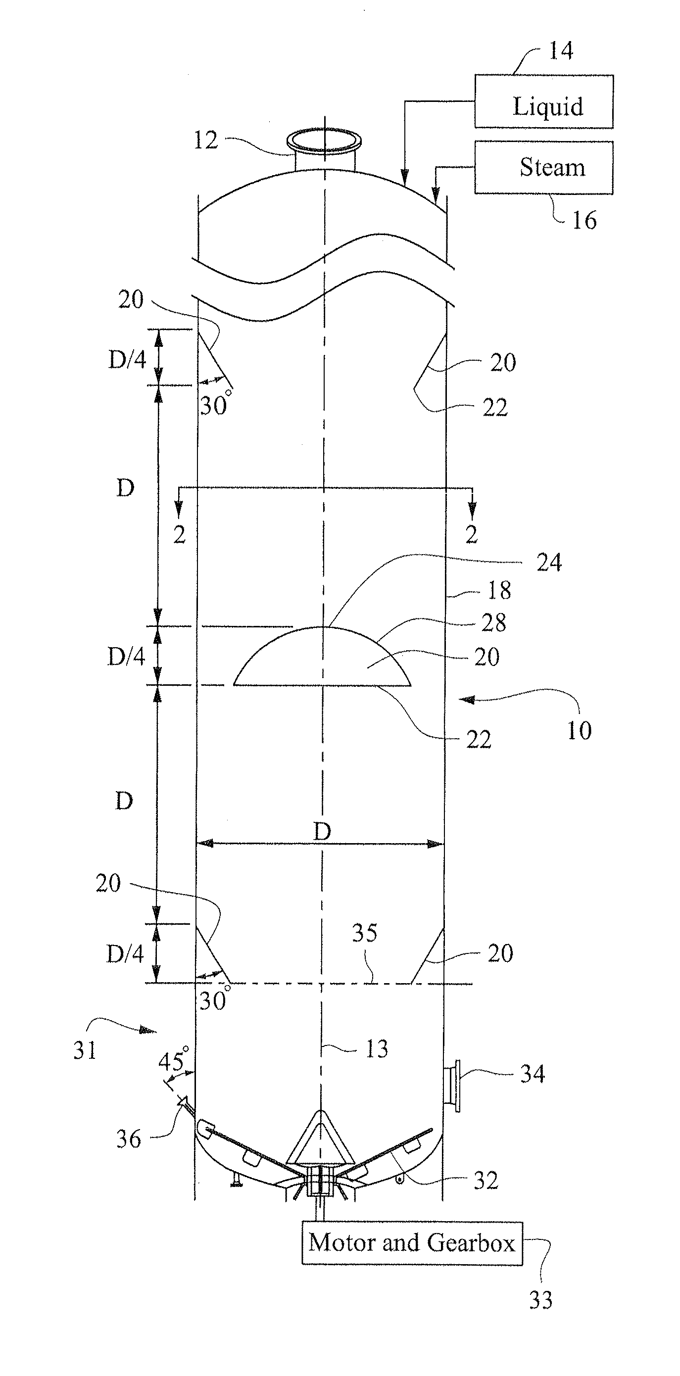
[0015]It is generally desired to maintain uniform conditions of the biomass in a reactor vessel, at least across any given elevation of the vessel. For example, it may be desired to achieve a uniform downward flow rate for all of the biomass in the vessel. It is typically not desired to have stagnate flow regions of biomass in the reactor vessel or columns of faster moving biomass in the reactor vessel. Similarly, the temperature in the reactor vessel is typically desired to be uniform across each elevation of the vessel. The temperature of the biomass may vary between different elevations, such as increasing as the biomass moves down through reactor vessel. Uniform flow throughout the reactor vessel and uniform temperature at each elevation in the reactor vessel promotes uniform processing of the biomass and a flow of biomass with uniform characteristics being output from the reactor vessel.
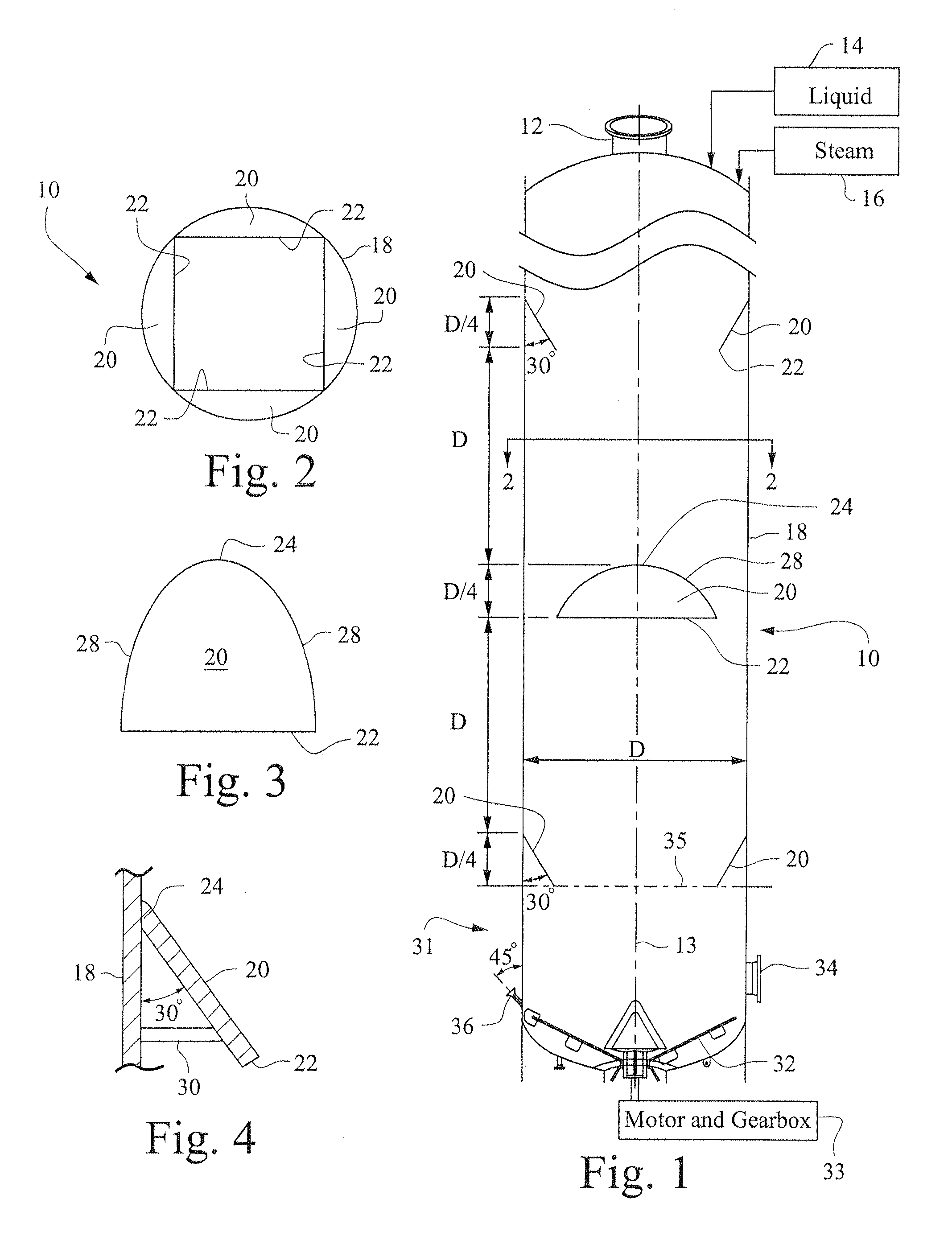
[0018]The rapid release of the compression as the biomass moves past the plates reduces the tendency of the biomass to arch and hang-up in the vessel. The single convergence formed by the plates minimizes the hang-ups that might otherwise occur with flow rings or other arrangements that are multi-dimensional convergence devices.
[0019]The pairs of plates at various elevations of a reactor vessel reduce compaction of the biomass especially at the bottom of the vessel. The reduction in compaction may be most pronounced in reactor vessels having little or no free liquid. The reduction in compaction lowers the risk of channeling or flow stoppage at the lower elevations in the reactor vessel. The reduction in compaction also reduces the torsional force needed to drive the scraper, screw conveyor or other outlet device at the bottom of the reactor vessel. The reduced torsional force allows for smaller motors and gearboxes needed to drive the outlet devices, such that the motor and gearboxes may be no larger than those required for reactor vessel with a liquid filled reaction vessel.
[0023]A method has been conceived to process biomass in a reactor vessel comprising: continuously feeding comminuted biomass to an upper inlet of the reactor vessel; continuously adding water or other liquor to the biomass such that a liquid level in the reactor vessel is substantially below an upper level of the biomass in the reactor vessel; treating the biomass in the reactor vessel; continuously discharging the treated biomass from a bottom outlet of the reactor vessel; as the biomass flows gradually and continuously downward in the reactor vessel from the upper level of the biomass to the bottom outlet, moving the biomass between a plurality of pairs of support plates, wherein (i) the pairs of support plates are arranged at different elevations in the vessel, (ii) the plates of each pair are mounted to sidewall of the vessel at a slope with respect to the sidewall that converges the plate inwardly towards an opposite plate along a downward direction, and (iii) the convergence of each pair of plates is along a single direction of convergence; gradually increasing compaction of the biomass as the biomass flows down between each pair of support plates; rapidly releasing some of the compressive forces on the biomass as the biomass flows pass lower edges on each pair of support plates.

Problems solved by technology

The high level of compaction of biomass tends to increase the risk that regions of the biomass will stagnate in the reactor vessel and other regions will form columns of fast moving biomass in the vessel.
The high compaction of the annual plant biomass can apply substantial mechanical loads in the lower portion of the reactor vessel and, particularly, on a discharge device at the bottom of the vessel.
These high mechanical loads may increase the energy required to operate the discharge device, such as by increasing the power needed to rotate a scraper in the bottom of the reactor.
If excessive, the high compaction may inhibit the operation of the discharge device.
Further, the high compaction may damage the discharge device, such as by bending the arms of a scraper.
However, high liquor content has drawn backs, such as reducing the amount of chips that move through the vessel and increasing the volume of liquor and chips to be pressurized and heated.
The high adsorption of liquid in the biomass reduces the amount of free liquid available to lubricate the flow of biomass through the reactor vessel.
The weight of saturated biomass creates large downward forces due to gravity in a reactor vessel.
The amount of compaction of biomass at the lower elevations in the reactor vessel tends to be high due to the large height difference between the level of biomass and the liquid level.
The lack of floating further compacts the biomass at the bottom of the reactor vessel.
In a reactor vessel processing annual plant biomass, the compaction can be excessive such that the material can hang up on the conical flow rings that extend around a vessel.
The reduction of the cross-sectional area may not be suitable for upper elevations of a vessel where a generally continuous cross-sectional area is desired to promote uniform flow conditions of the biomass moving down through the vessel.

Method used


Image

  • Reactor vessel having single convergence sidewall plates
  • Reactor vessel having single convergence sidewall plates

Examples


Embodiment Construction

[0028]FIG. 1 is a cross-sectional view taken along a vertical plane of a reactor vessel 10 having an upper inlet 12 for biomass, such as annual plant biomass. FIG. 2 shows in cross-section along a horizontal plane the vessel 10 from a top down viewpoint.

[0029]The vessel 10 may be adapted to process annual plant biomass, such as straw. The upper inlet 12 may include a top separator, screw conveyor or other transport mechanism to move biomass into the reactor vessel. Liquid, such as water or clear liquor, may be added to the top of the vessel with the incoming flow of biomass or through a liquid inlet 14. Steam or another heated gas may be added to the vessel, such as through heat inlet 16. The steam or other gas may also be added to elevate the pressure in the vessel to an internal pressure above atmospheric, such as 10 to 20 psig or greater.

[0030]The reactor vessel 10 is illustrated in FIG. 1 as having a constant diameter (D) and oriented vertically along a vertical axis 13. The rea...


PUM

PropertyMeasurementUnit
angleaaaaaaaaaa
angleaaaaaaaaaa
diameteraaaaaaaaaa

Abstract

A reactor vessel including: an upper inlet and a bottom discharge; a generally vertically oriented sidewall between the upper inlet and bottom discharge, wherein the sidewall defines a perimeter of an interior flow passage in the vessel; a first pair of support plates arranged on opposite sides of the sidewall, wherein the first pair of support plates reduces a cross-sectional flow area of the flow passage in a first single direction of convergence, and a second pair of support plates arranged on opposite sides of the side wall, wherein the second pair of support plates reduces a cross-sectional flow are of the flow passage in a second single direction of convergence, wherein the second single direction is angularly offset to the first single direction, and the second pair of support plates is at a different elevation of the vessel than the first pair of support plates.

Description

RELATED APPLICATION[0001]This application claims the benefit of U.S. provisional application Ser. No. 61 / 467,419 filed Mar. 25, 2011, which is incorporated in its entirety by reference.BACKGROUND[0002]The invention relates to vessels for biomass and particularly to vessels having internal structures to prevent excessive compression of the biomass within the vessel.[0003]Reactor vessels are used to treat biomass to dissolve carbohydrates or lignin or other components of the biomass to produce pulp, fuels or chemicals. Reactor vessels may be large, vertically oriented and pressurized. A typical reactor vessel may have a height of greater than 100 feet (33 meters) and a diameter of at least 30 feet (10 meters). A reactor vessel may be cylindrical with a closed top and bottom sections. An inlet to reactor vessel may be at the top section and may include a top separator device to remove a portion of liquor from the biomass as it enters the reactor vessel. An outlet from the reactor vesse...

Claims


Application Information

Patent Timeline
Patent Type & Authority Applications(United States)
IPC IPC(8): B01J19/00C09K3/00
CPCB01J19/18B01J2219/00123B01J2219/0077B01J2219/00774D21C7/08B01J2219/185D21C7/00C10G1/04B01J2219/00779
Inventor JOHANSON, JERRY R.
Owner ANDRITZ INC
Learn More