Chip card holder with protective cover for portable electronic devices

a technology for electronic devices and chip cards, applied in the direction of instruments, casings/cabinets/drawers, electrical equipment, etc., can solve the problems of troublesome operation of removing the protective cover, easy loss of tools, and affecting the appearan

Inactive Publication Date: 2013-12-19
SHENZHEN FUTAIHONG PRECISION IND CO LTD +1
View PDF27 Cites 14 Cited by
  • Summary
  • Abstract
  • Description
  • Claims
  • Application Information

AI Technical Summary

Problems solved by technology

However, the hole in the portable electronic device affects the appearance.
In addition, t

Method used


Image

  • Chip card holder with protective cover for portable electronic devices
  • Chip card holder with protective cover for portable electronic devices
  • Chip card holder with protective cover for portable electronic devices

Examples


Embodiment Construction

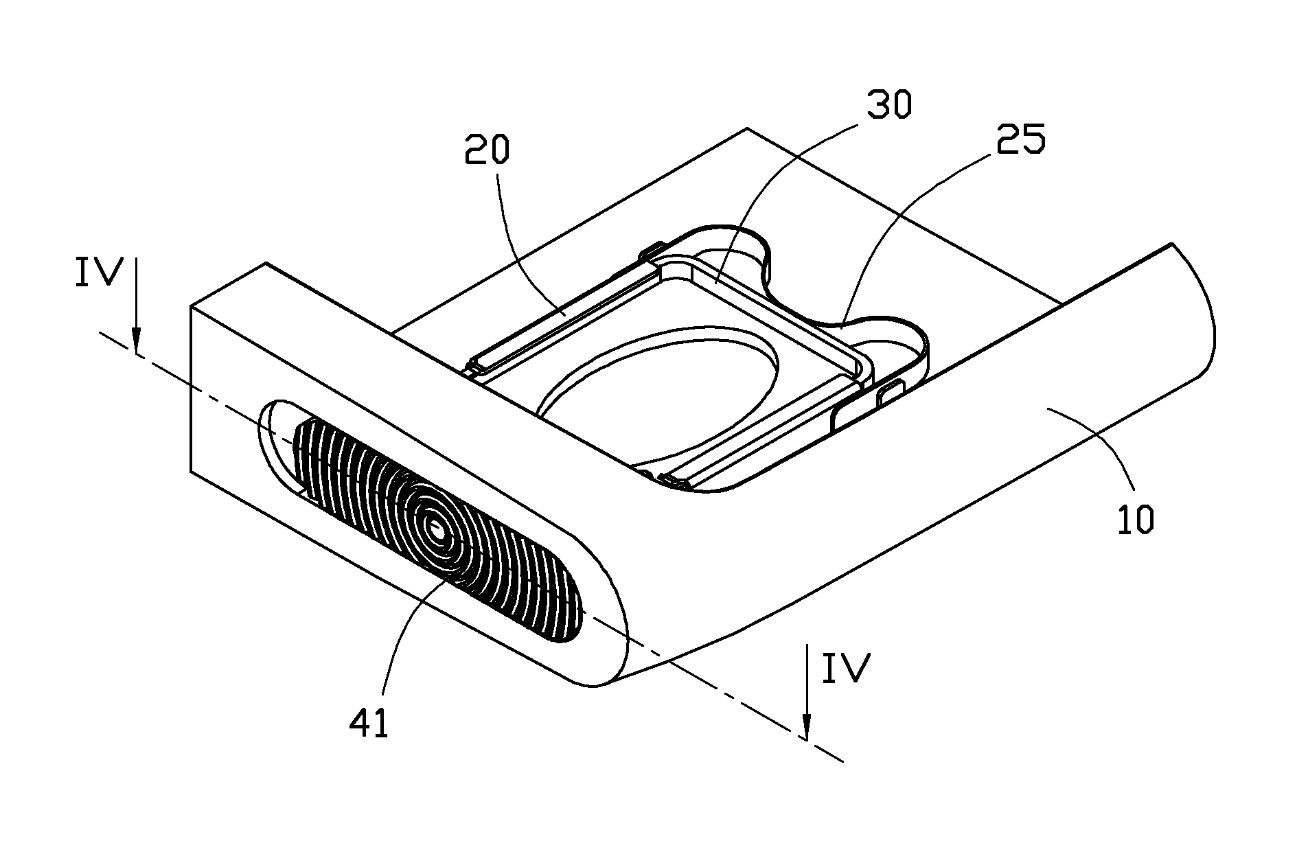
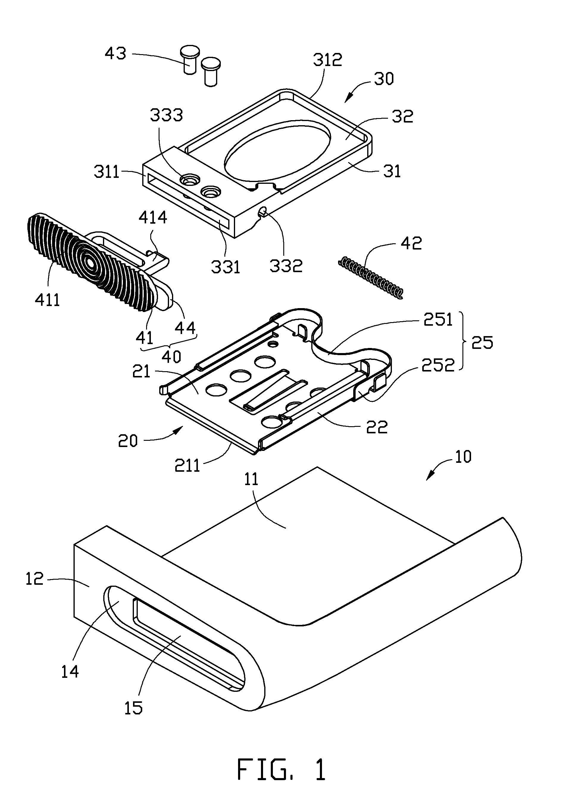
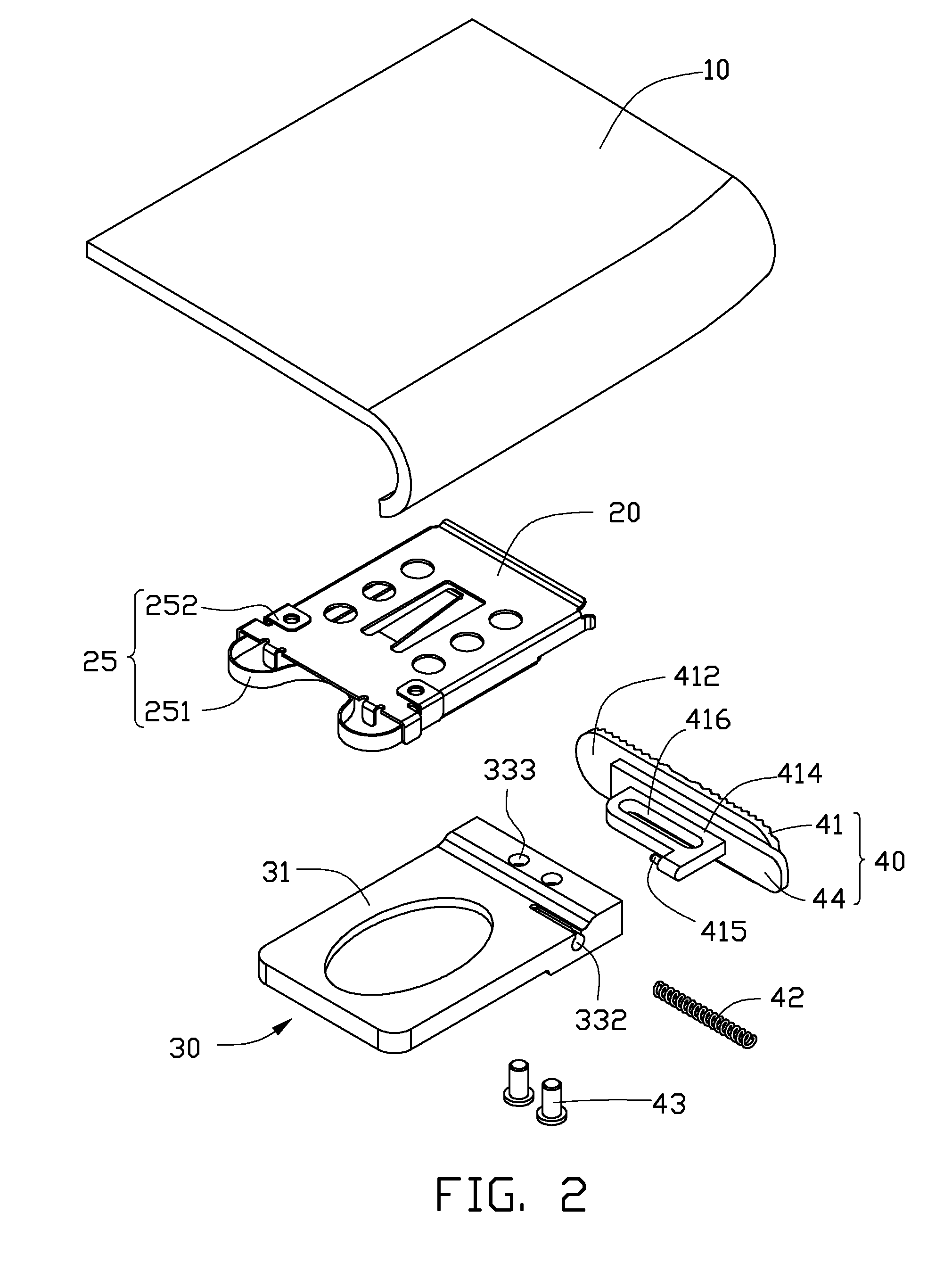
[0014]Referring to FIGS. 1 to 3, shown is an exemplary embodiment of a chip card holder which can be used in a portable electronic device, such as a cellular phone or any electronic device where a chip card is required. The portable electronic device includes a housing 10. The chip card holder is assembled in the housing 10. A chip card (not shown) can be selectively placed in the chip card holder. The chip card may be a subscriber identity module (SIM) card or a flash card.

[0015]The chip card holder includes a receiving frame 20, an ejecting member 25, a tray 30, a protective cover 40, an elastic member 42, and two fasteners 43.

[0016]The housing 10 may be a portion of the portable electronic device or a separate element fixed to the portable electronic device. In this exemplary embodiment, the housing 10 is a top portion or a bottom portion of the portable electronic device. The housing 10 includes a main body 11 and an end wall 12 integrated with the main body 11. The end wall 12 ...


PUM


Abstract

A chip card holder includes a housing defining a hole, a receiving frame, an ejecting member, a tray, an elastic member, and a protective cover. The receiving frame is mounted on the housing. The ejecting member is positioned at one end of the receiving frame. The tray is slidably received in the receiving frame and is abutted by the ejecting member. The elastic member is positioned between the tray and the protective cover. The protective cover is slidably connected to the tray and covers the hole. After the protective cover is slid along the housing and is unlocked from the housing, the ejecting member ejects the tray from the housing.

Description

BACKGROUND[0001]1. Technical Field[0002]The present disclosure relates to chip card holders, and particularly to a chip card holder with a protective cover for portable electronic devices.[0003]2. Description of Related Art[0004]With the development of wireless communication and information processing technologies, portable electronic devices such as mobile phones are now widely used. Surface contact cards are necessary elements in portable electronic devices.[0005]A conventional chip card holder includes a protective cover, which is directly exposed from housings of the portable electronic device. The exposed cover defines a hole for convenient insertion and removal of the surface contact card with a tool. However, the hole in the portable electronic device affects the appearance. In addition, the tool is easily lost, and the operation of removing the protective cover is troublesome.[0006]Therefore, there is room for improvement within the art.BRIEF DESCRIPTION OF THE DRAWINGS[0007...

Claims


Application Information

Patent Timeline
IPC IPC(8): H05K7/14H05K5/03
CPCH05K7/1461H05K5/03H05K5/0286
Inventor GAO, YAN-LING
Owner SHENZHEN FUTAIHONG PRECISION IND CO LTD
Why Eureka
Try Eureka