Lamp structure

Inactive Publication Date: 2013-12-19
TAIWAN FU HSING INDAL
View PDF1 Cites 4 Cited by
  • Summary
  • Abstract
  • Description
  • Claims
  • Application Information

AI Technical Summary

Benefits of technology

The present invention is a lamp structure with a heat dissipation tube to improve LED lamp efficiency and prevent overheating. The structure includes a case, fixing base, heat dissipation tube, lighting module, and insulating sleeve. The heat dissipation tube is connected to the fixing base and a space is created between the tube and the shell of the case for heat transfer. The lighting module is placed on the fixing base and an insulating sleeve is added for safety. The insulating sleeve contains a conductive wire for electrical connection with the lighting module. By having this heat dissipation space, the LED lamps can efficiently transfer and dissipate heat, leading to improved opto-electronic conversion efficiency.

Problems solved by technology

The lamp structure 10 produces massive heat and is unable to dissipate heat when the lamp structure 10 is in use, which results in a lower lighting efficiency or destruction through rising temperature of the light emitting device 12.

Method used


Image

  • Lamp structure
  • Lamp structure
  • Lamp structure

Examples


Embodiment Construction

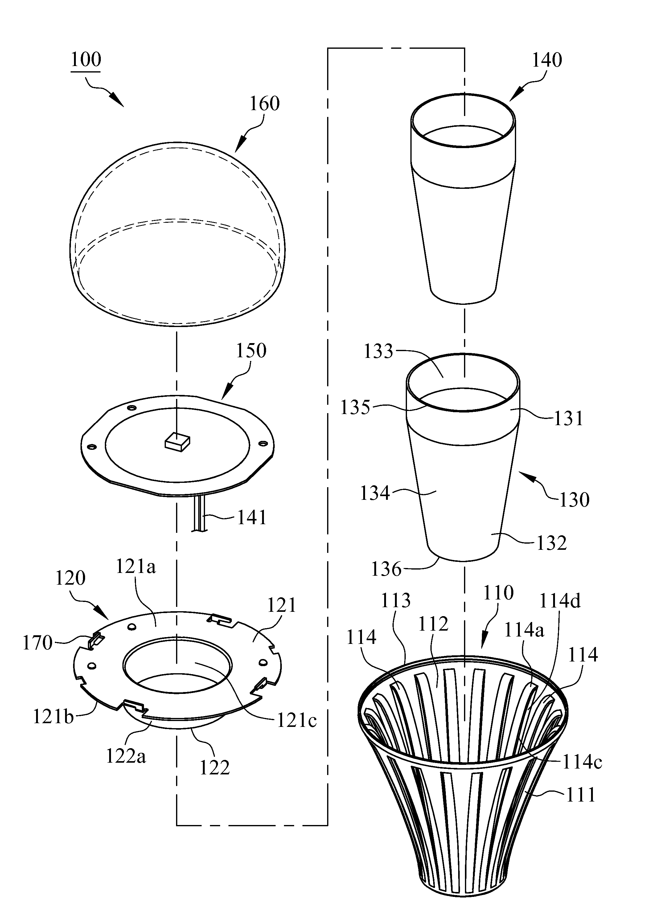
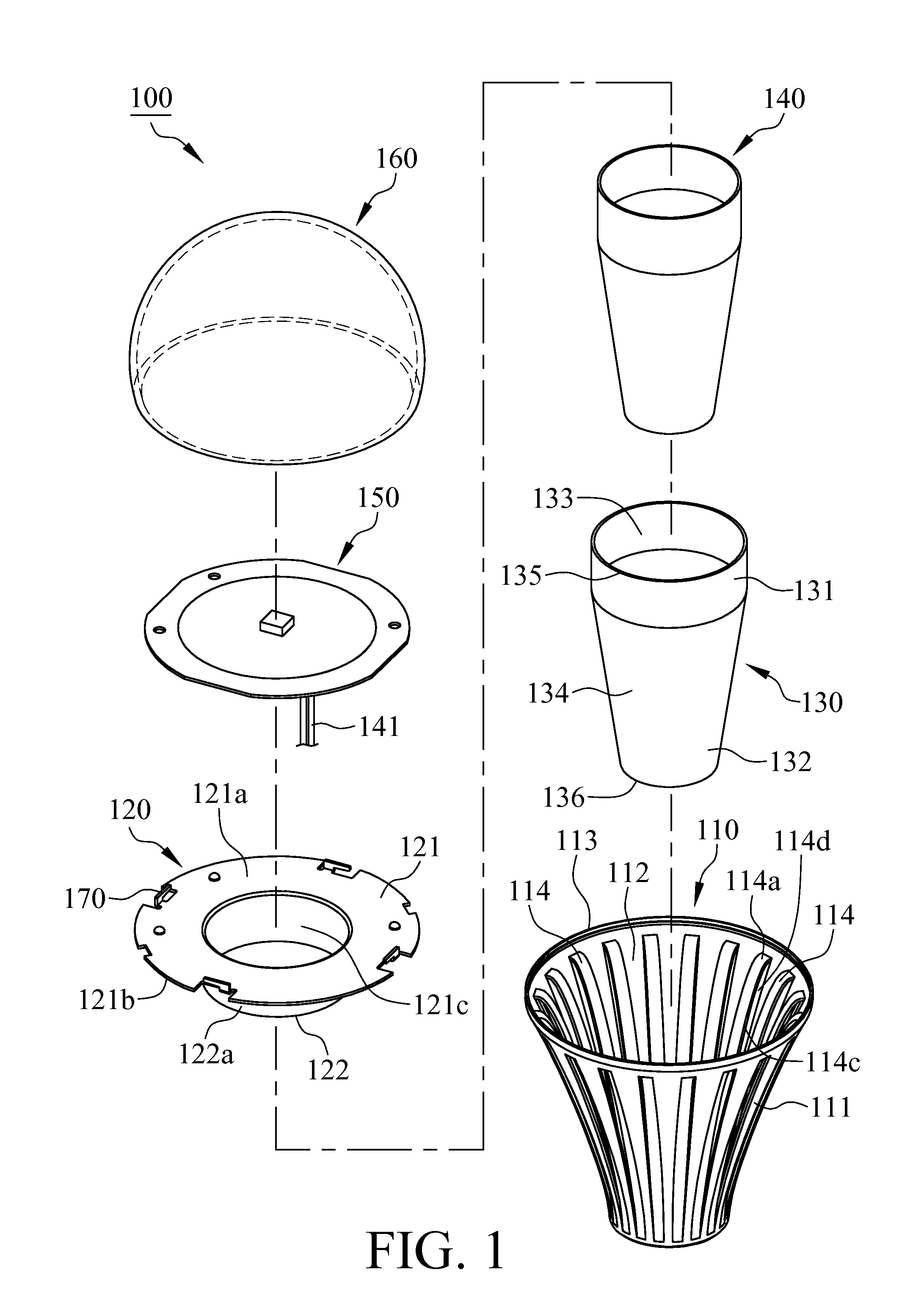
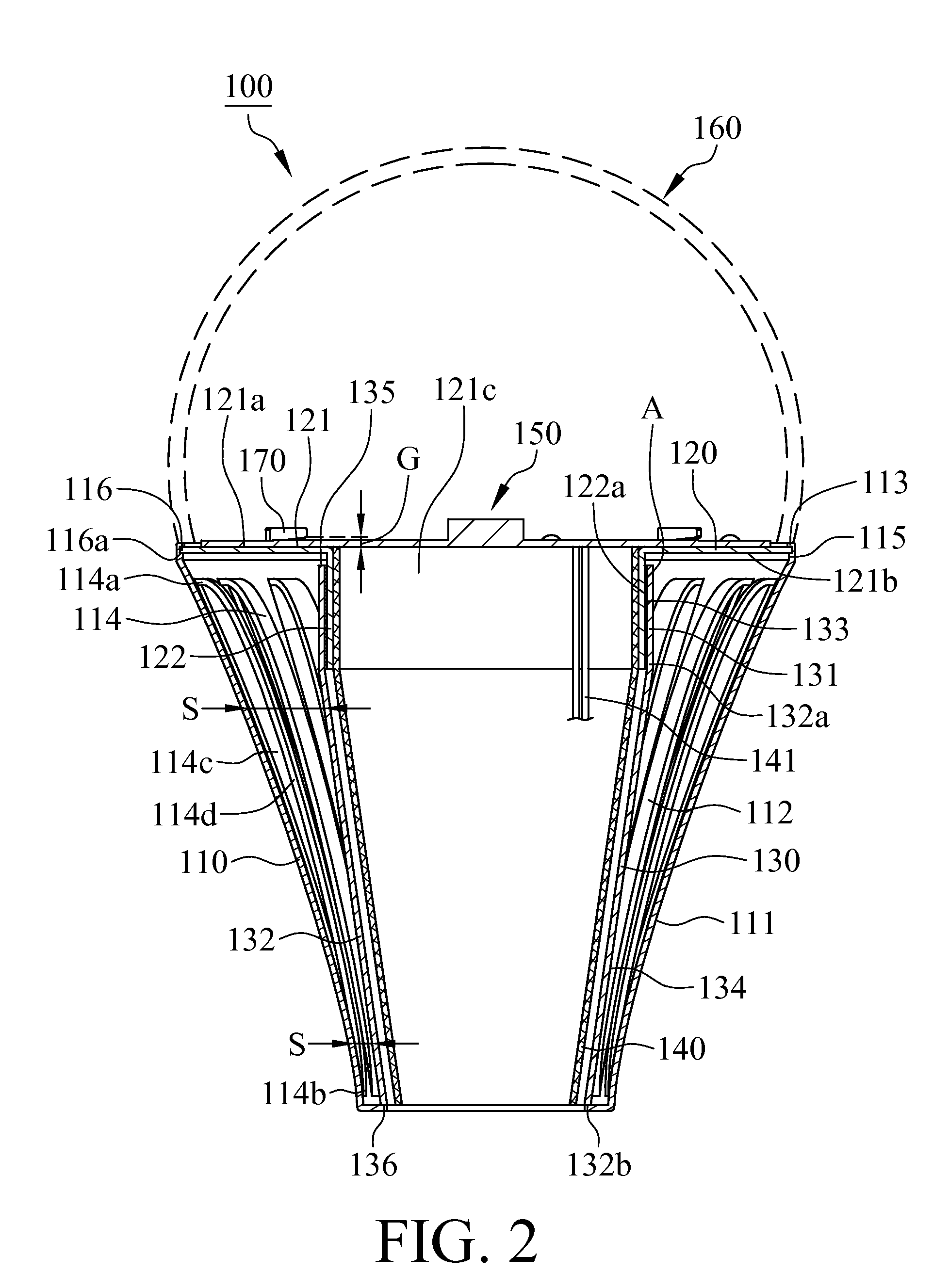
[0016]With reference to FIGS. 1 and 2, a lamp structure 100 in accordance with a first embodiment of the present invention includes a case 110, a fixing base 120, a heat dissipation tube 130, an insulating sleeve 140 and a lighting module 150. The case 110 comprises a shell 111, an accommodating chamber 112 surrounded by the shell 111, a clamping portion 113 formed at the shell 111 and a plurality of fin plates 114, wherein the fin plates 114 are formed as one piece with the case 110 by means of stamping. The fin plates 114 protrude toward the accommodating chamber 112, wherein a top end 114a and a bottom end 114b of each fin plate 114 are in connection with the shell 111, and a lateral edge 114c of each fin plate 114 is not in connection with the shell 111 so as to form a gap 114d. The fixing base 120 is disposed at the case 110 and comprises a carrier 121 and an extending portion 122. The clamping portion 113 of the case 110 is bendable toward the accommodating chamber 112 and cla...


PUM


Abstract

A lamp structure includes a case, a fixing base, a heat dissipation tube, a lighting module and an insulating sleeve. The fixing base is disposed at the case and comprises a carrier, and the lighting module is disposed on the carrier. The heat dissipation tube is coupled to the fixing base, and a heat dissipation space is defined between the heat dissipation tube and the case. The insulating sleeve is coupled to the fixing base. The heat produced by the lighting module can be conducted to the heat dissipation tube and the heat dissipation space through the fixing base to increase heat dissipation efficiency of the lamp structure.

Description

FIELD OF THE INVENTION[0001]The present invention is generally related to a lamp structure, which particularly relates to the lamp structure with a heat dissipation tube.BACKGROUND OF THE INVENTION[0002]With reference to FIG. 11, a convention lamp structure 10 includes a substrate 11, a light emitting device 12, a base 13 and a lamp cover 14. The light emitting device 12 is disposed on the substrate 11, and the substrate 11 is disposed on the base 13. The lamp structure 10 produces massive heat and is unable to dissipate heat when the lamp structure 10 is in use, which results in a lower lighting efficiency or destruction through rising temperature of the light emitting device 12.SUMMARY[0003]The primary object of the present invention is to provide a lamp structure with a heat dissipation tube to overcome a lower lighting efficiency or destruction of a conventional LED lamp caused by overheat while the LED lamp is in use.[0004]A lamp structure in the present invention includes a ca...

Claims


Application Information

Patent Timeline
IPC IPC(8): F21V29/00
CPCF21V29/15F21V29/773F21V29/83F21K9/232F21Y2115/10
Inventor WU, SHUN-HOHUANG, CHIH-CHENG
Owner TAIWAN FU HSING INDAL
Why Eureka
Try Eureka