Method and Apparatus for a Right-Sided Short Sheath

a technology of introducer and short sheath, which is applied in the field of introducers, can solve the problems of unavoidably torqued or rotating introducer, loss of intended implanted position, and inability to use the following telescopic introducer

Inactive Publication Date: 2013-12-19
PRESSURE PROD MEDICAL SUPPLIES INC
View PDF4 Cites 2 Cited by
  • Summary
  • Abstract
  • Description
  • Claims
  • Application Information

AI Technical Summary

Problems solved by technology

It is also common to access the heart from the right subclavian vein when left sided access is not practical.
The problem of the prior art is to provide a cardiac introducer which can reliably and easily deliver pacing leads and catheters into the coronary sinus of the heart, from the right side (preferably from the right subclavian vein, or alternatively the right axillary or right cephalic vein), and subsequently removed without dislodging a permanent pacing lead delivered through the introducer.
An additional problem is that the junction in many, if not most, patients between the right subclavian vein and the superior vena cava can approach that of a right angle.
A straight introducer or catheter being inserted through this vascular junction can then easily be kinked, which renders it subsequent use as a telescopic introducer impractical or impossible.
As the conventional introducer is removed from the pacemaker lead the bias built into the curvature of the steerable introducer in combination with the typical curvatures encountered in the human right subclavian-to-superior-vena-cava path are such that the introducer is unavoidably torqued or rotates.
This in turn causes the pacemaker lead, which has been implanted into the coronary ostium or coronary sinus, to pull out at least to some degree so that the intended implanted position is lost.
Secondly, this prior art introducer also did not avoid, when removed, applying a twisting torque applied to a pacemaker lead disposed through it.
The prior art introducer was found to be unacceptably difficult to steer and manipulate to achieve access from the right side subclavian vein into the coronary sinus and thus was regarded as a difficult-to-use device.

Method used


Image

  • Method and Apparatus for a Right-Sided Short Sheath
  • Method and Apparatus for a Right-Sided Short Sheath
  • Method and Apparatus for a Right-Sided Short Sheath

Examples


Embodiment Construction

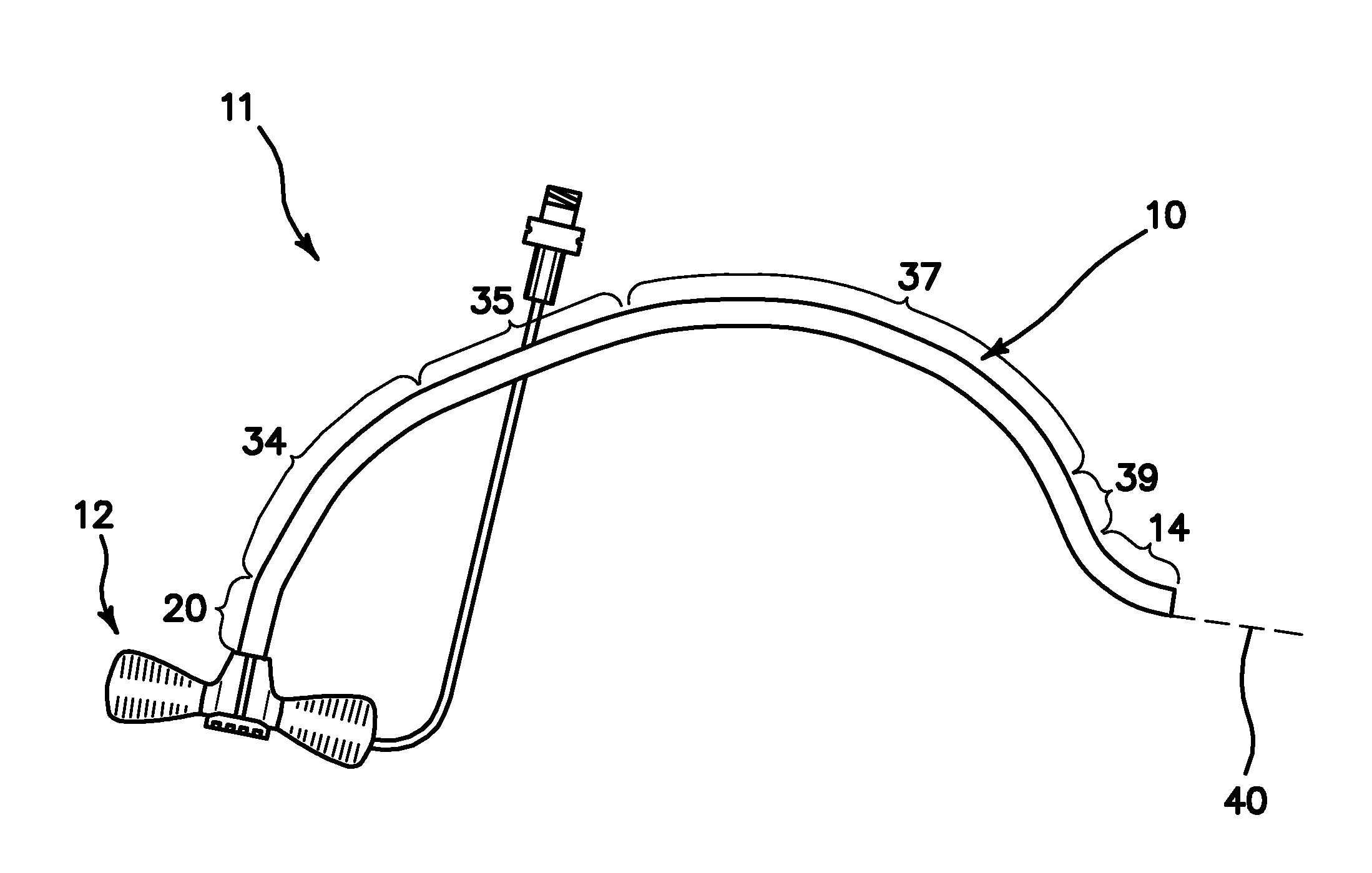
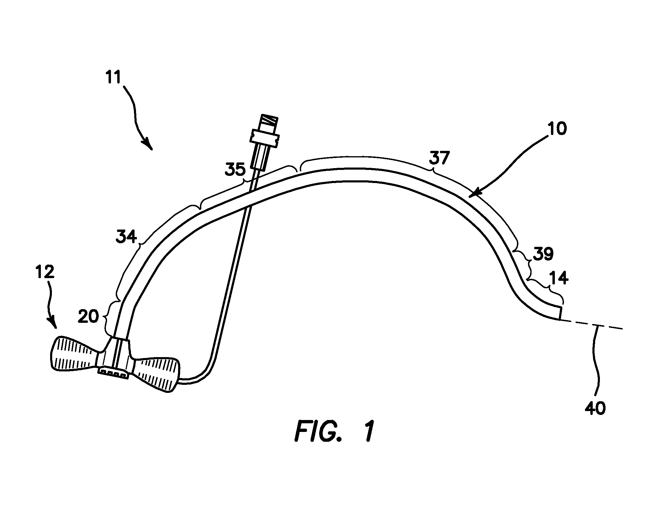
[0039]FIG. 1 is a side plan view of a prebiased, right sided short sheath or cardiac introducer 11, which includes a separable valve or hub 12 and a curved sheath 10 used to access the right atrium from the right subclavian vein. Sheath 10 is a separable introducer 11 as is well known to the art, i.e. it may be longitudinal separated by splitting, tearing, cutting or any other means of separation so that it may be removed over the hub or other obstruction of a pacemaker lead or other elongate tool that may be telescopically disposed through it. Sheath 10 may be longitudinally separated by use of molecular lines of weakening in the walls of the sheath 10, grooves or indentations defined into sheath 10 or any other means now known or later devised for allowing longitudinal separation. However, the scope of the invention also includes the possibility that sheath 10 may be torqueable by being braided or otherwise reinforced so that the use of a cutting tool may then be required into ord...


PUM


Abstract

An introducer sheath comprising a curved shape that follows the right sided vasculature when introduced through the right side subclavian vein and which stops far short of the coronary ostium in the right atrium. No attempt is made to access the coronary sinus through the sheath. The sheath establishes a fulcrum point on the upper lateral wall of the superior vena cava and comprises the ability to be removed from the implanted pacemaker lead without flipping the distal end of the sheath to cause a pull back of the pacemaker lead. The more proximal portions of the sheath extend through the superior vena cava and provide a force which biases the sheath against the lateral wall of the lower portion of the superior vena cava to establish a fulcrum or pivot point which positions the distal end of sheath at the desired location.

Description

RELATED APPLICATIONS[0001]The present application is related to U.S. Provisional Patent Application Ser. No. 61 / 440,250, filed on Feb. 7, 2011, which is incorporated herein by reference and to which priority is claimed pursuant to 35 USC 120.BACKGROUND[0002]1. Field of the Technology[0003]The disclosure relates to the field of introducers for delivering pacing leads and catheters into the heart, and more particularly into the coronary sinus of the heart with the access point being from the right subclavian vein (alternatively the right axillary or right cephalic vein), and subsequently being removed from the vein without dislodging the lead(s) or catheter(s) delivered through the introducer.[0004]2. Description of the Prior Art[0005]It is a routine procedure to provide access and delivery of pacing leads and catheters into the heart from the left subclavian vein, left axillary vein, or left cephalic vein for placement of devices into the right atrium, right ventricle or coronary sin...

Claims


Application Information

Patent Timeline
Patent Type & Authority Applications(United States)
IPC IPC(8): A61B17/34A61M25/00
CPCA61B17/3421A61M25/0041A61B17/3468A61B2017/00243A61M25/0668A61M2025/0681A61N1/056
Inventor WORLEY, SETHKURTH, PAULARMOUR, ANDREW
Owner PRESSURE PROD MEDICAL SUPPLIES INC
Why Eureka
Try Eureka