

Propfan engine
- Summary
- Abstract
- Description
- Claims
- Application Information
AI Technical Summary
Benefits of technology
Problems solved by technology
Method used
Image

Examples
Embodiment Construction
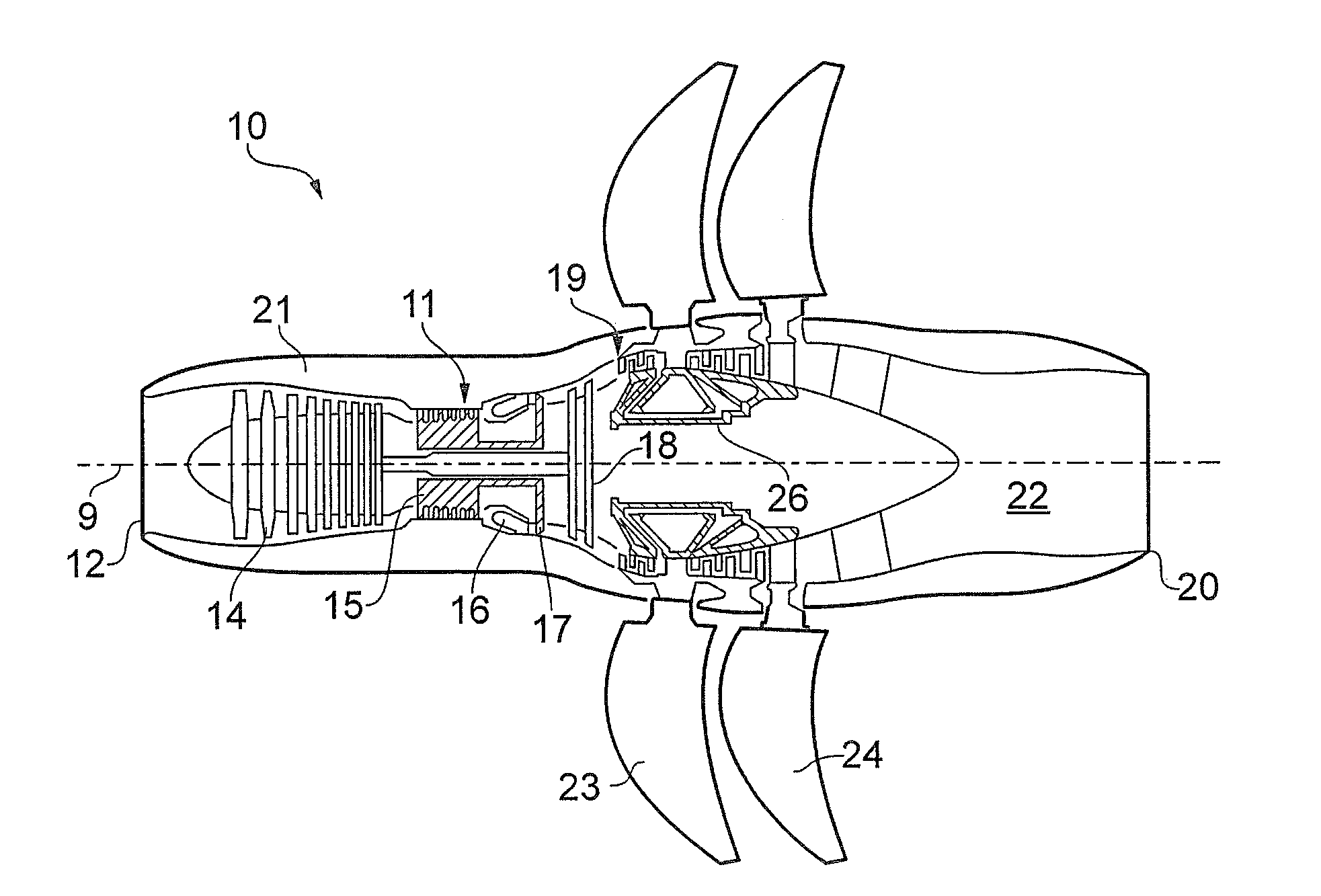
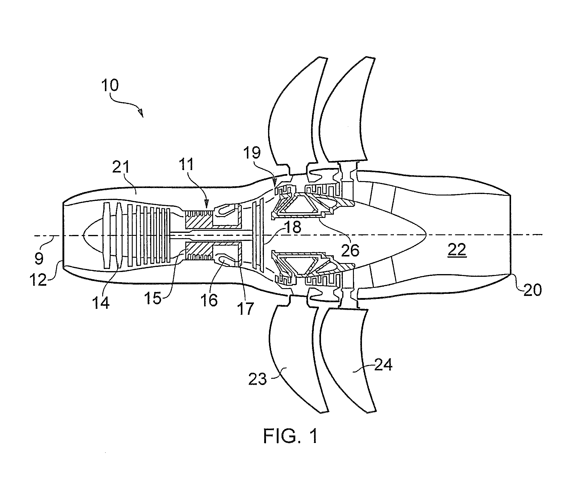
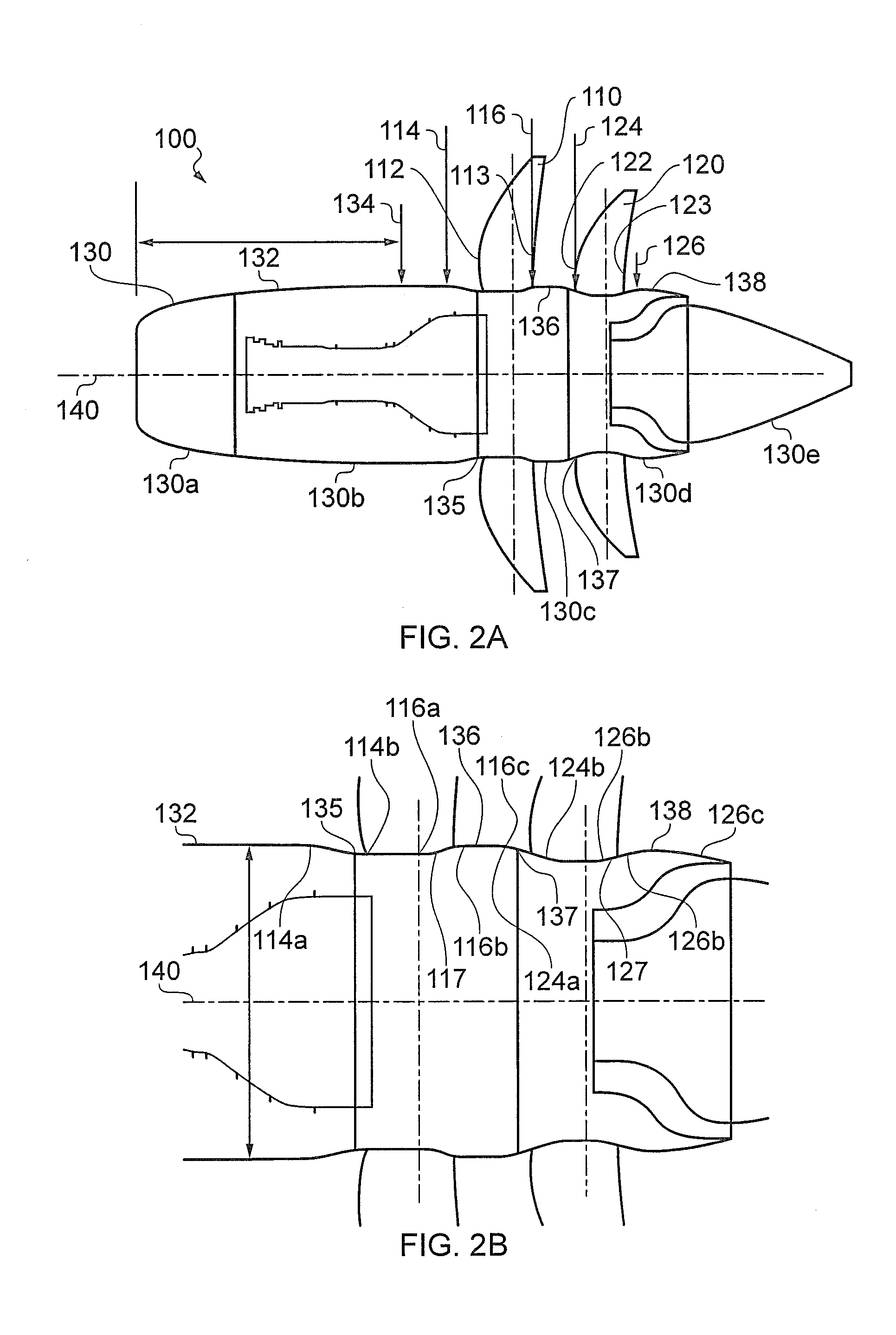
[0033]With reference to FIGS. 2(a) and 2(b), a propfan engine 100, e.g. an unducted turbofan engine, according to an example of the present disclosure, may comprise first and second rotor stages 110, 120 each comprising a plurality of rotors. As shown, the propfan engine may be a pusher type, e.g. the first and second rotor stages 110, 120 may be towards the rear of the engine. However, in an alternative configuration the propfan engine may be a puller type, e.g. the first and second rotor stages may be towards the front of the engine.
[0034]The propfan engine may further comprise an outer wall 130, e.g. nacelle, comprising an outer profile 132. The outer wall 130 may comprise one or more constituent elements. For example, first and second elements 130a, 130b may form a fixed, e.g. non-rotating, portion of the outer wall upstream of the first and second rotors 110, 120. The first element 130a may comprise an inlet cowl and the second element 130b may comprise one or more access doors...
PUM
 Abstract
Description
Claims
Application Information