Storage Facility

Active Publication Date: 2017-03-02
DAIFUKU CO LTD
View PDF1 Cites 7 Cited by
  • Summary
  • Abstract
  • Description
  • Claims
  • Application Information

AI Technical Summary

Benefits of technology

[0016]Then, by disposing the plurality of vertical pipes constituting the gas supply portion so as to be distributed according to the arrangement of the plurality of struts, it is possible to reduce the diameter of each individual vertical pipe. Accordingly, the plurality of vertical pipes for supplying the inactive gas to the gas inlets provided individually on the placement portions can be provided in the peripheral region of each of the plurality of struts d

Problems solved by technology

As a result, the storage efficiency of the storage rack is reduced by th

Method used


Image

  • Storage Facility
  • Storage Facility
  • Storage Facility

Examples


Embodiment Construction

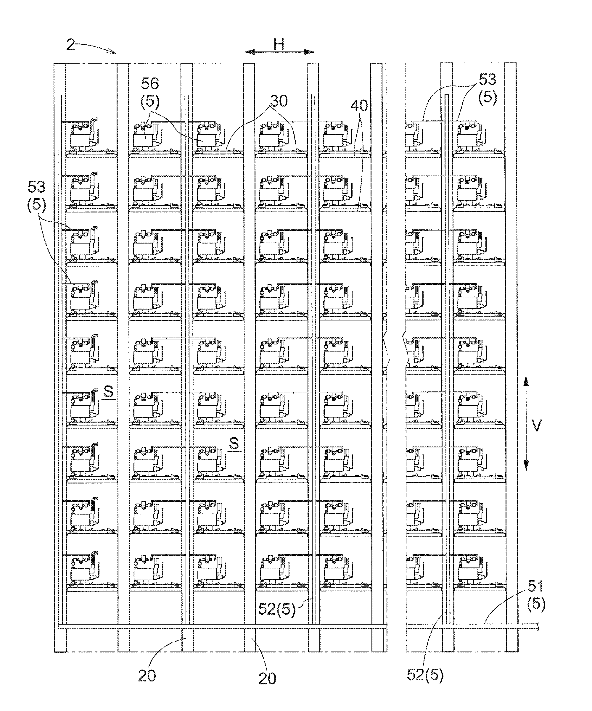
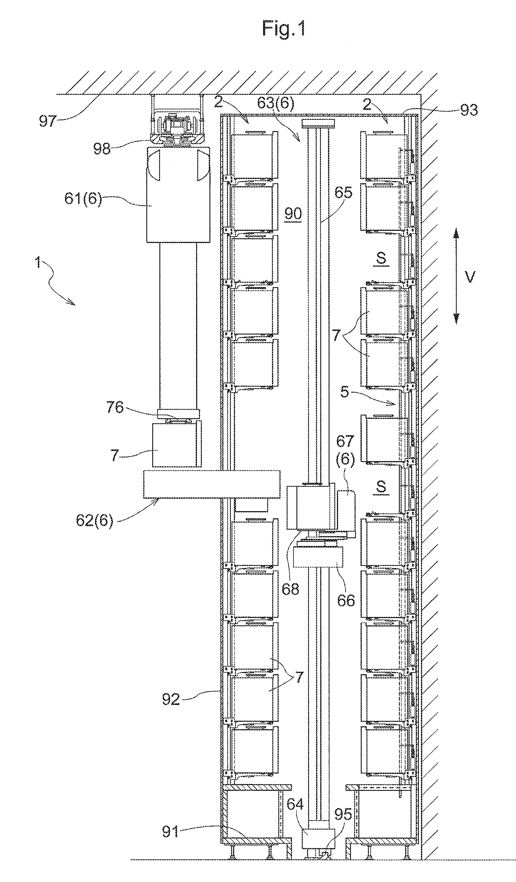
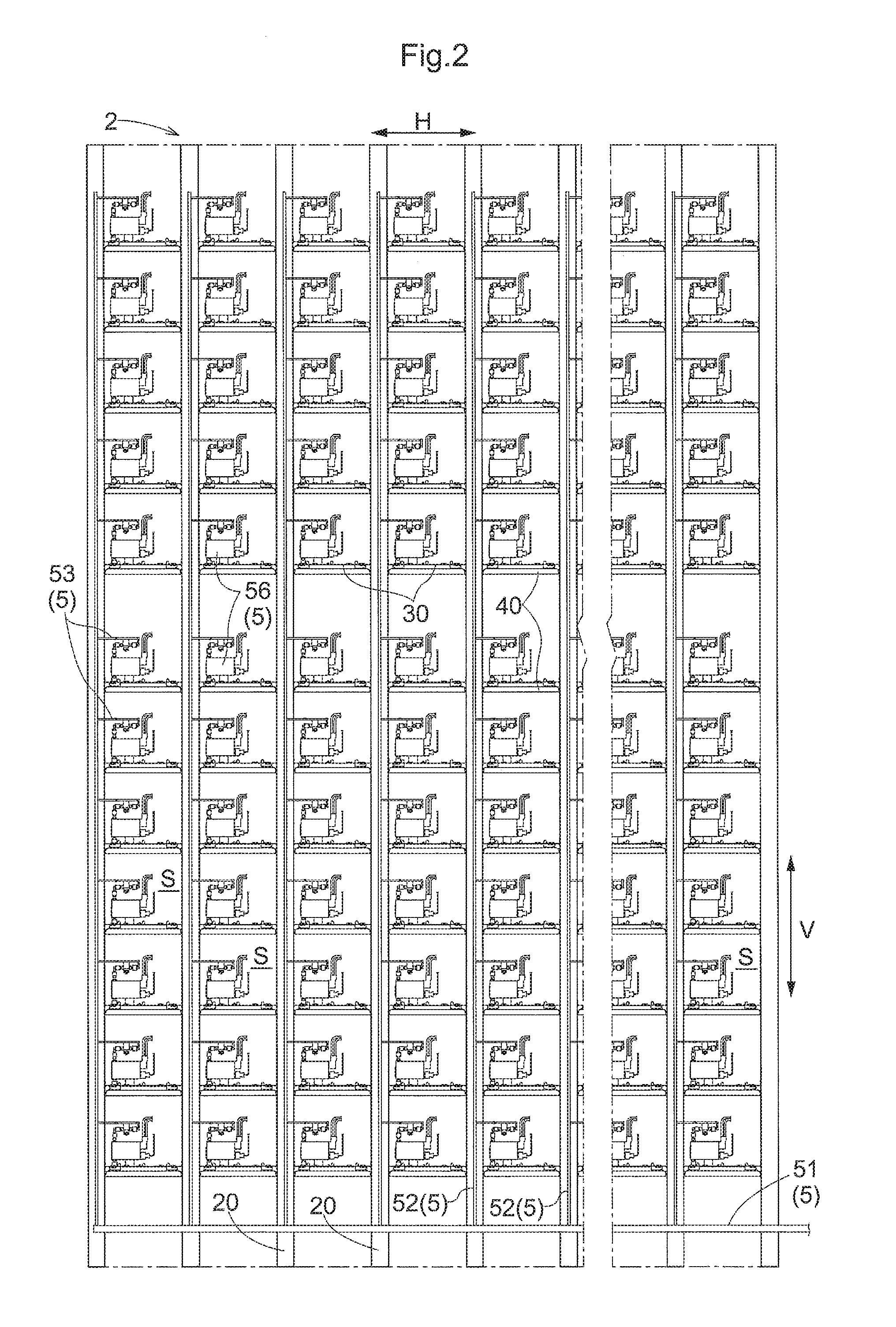
[0025]A storage facility according to an embodiment will now be described. The present embodiment describes, as an example, a storage facility 1 that stores containers 7 accommodating semiconductor substrates constituted by semiconductor wafers or the like as storage articles. The storage facility 1 of the present embodiment is installed, for example, in a clean room, and is used, for example, for temporarily storing raw materials or intermediate products, for example, during a waiting time before they are subjected to the next step in the manufacturing process of a semiconductor product. The storage function of the storage facility 1 is mainly realized by storage racks 2 each including a plurality of storage sections S. In the following, the storage facility 1 and the storage racks 2 of the present embodiment will be described in detail.

[0026]In the following description, an up-down direction V, a left-right direction H, and a front-rear direction D are each defined with respect to...


PUM


Abstract

A storage facility includes a storage rack including a plurality of storage sections and a gas supply portion that supplies an inactive gas to containers stored in the storage sections. Struts are installed at left and right ends of the storage rack and between adjacent ones of the storage sections, and placement portions are fixed to mutually adjacent ones of the struts. Each vertical pipe included in the gas supply portion is fixed to one of the struts to which the placement portion to which the inactive gas is supplied by the vertical pipe is fixed.

Description

CROSS-REFERENCE TO RELATED APPLICATION[0001]This application claims priority to Japanese Patent Application No. 2015-173251 filed Sep. 2, 2015, the disclosure of which is hereby incorporated in its entirety by reference.FIELD OF THE INVENTION[0002]The present invention relates to a storage facility that stores various types of articles.BACKGROUND[0003]A storage facility is used for temporarily storing raw materials or intermediate products, for example, during a waiting time before they are subjected to the next step in the manufacturing process of industrial products, for example. In this case, for example, when the industrial products are semiconductor products and storage articles are containers accommodating semiconductor substrates, in order to avoid surface contamination of the semiconductor substrates during storage, a storage facility configured to purge the stored containers with an inactive gas is used. As an example, the storage facility disclosed in JP 2015-009912A inclu...

Claims


Application Information

Patent Timeline
IPC IPC(8): H01L21/67H01L21/677
CPCH01L21/67769H01L21/67017H01L21/67389H01L21/67393H01L21/67775
Inventor OMORI, KAZUYAKAWAMURA, SHINSUKE
Owner DAIFUKU CO LTD
Why Eureka
Try Eureka