Compressor housing for turbocharger

Inactive Publication Date: 2018-10-04
OTICS CORP +1
View PDF4 Cites 8 Cited by
  • Summary
  • Abstract
  • Description
  • Claims
  • Application Information

AI Technical Summary

Benefits of technology

[0012]In the compressor housing for a turbocharger, the abradable seal is press-fitted into the press-fitting recessed portion of the abradable seal fixing part in the axial direction and the press-fit abutting portion abuts against the inner circumferential surface of the press-fitting recessed portion while the bulging portion located at a forward side of the press-fit abutting portion with respect to the press-fitting direction is fixed to the abradable seal fixing part, opposing to the grooved portion of the abradable seal fixing part. At an initial stage of assembly, the press-fit abutting portion of the abradable seal is press-fitted in the press-fitting recessed portion, and the diameter of the press-fit abutting portion is reduced by compressive stress from the inner circumferential surface of the press-fitting recessed portion, thereby providing a sufficient interference between the abradable seal and the inner circumferential surface of the press-fitting recessed portion, so that the abradable seal is held by the abradable seal fixing part. Furthermore, since the bulging portion of the abradable seal has an outside diameter larger than the inside diameter of the press-fitting recessed portion of the abradable seal fixing part but smaller than the inside diameter of the grooved portion, the bulging portion does not abut on the abradable seal fixing part. Therefore, a hollow space is formed in the radial direction between the bulging portion and an inner wall surface of the grooved portion. Consequently, whereas the press-fit abutting portion is subjected to compressive stress from the inner circumferential surface of the press-fitting recessed portion in the abradable seal fixing part, the bulging portion receives no compressive stress from the abradable seal fixing part after assembled. And, in the press-fitting direction (axial direction), the bulging portion is located at a forward side of the pr

Problems solved by technology

However, if the gap is decreased, the impeller may be damaged, for example, when the impeller blades come into contact w

Method used


Image

  • Compressor housing for turbocharger
  • Compressor housing for turbocharger
  • Compressor housing for turbocharger

Examples


Example

Embodiment 1

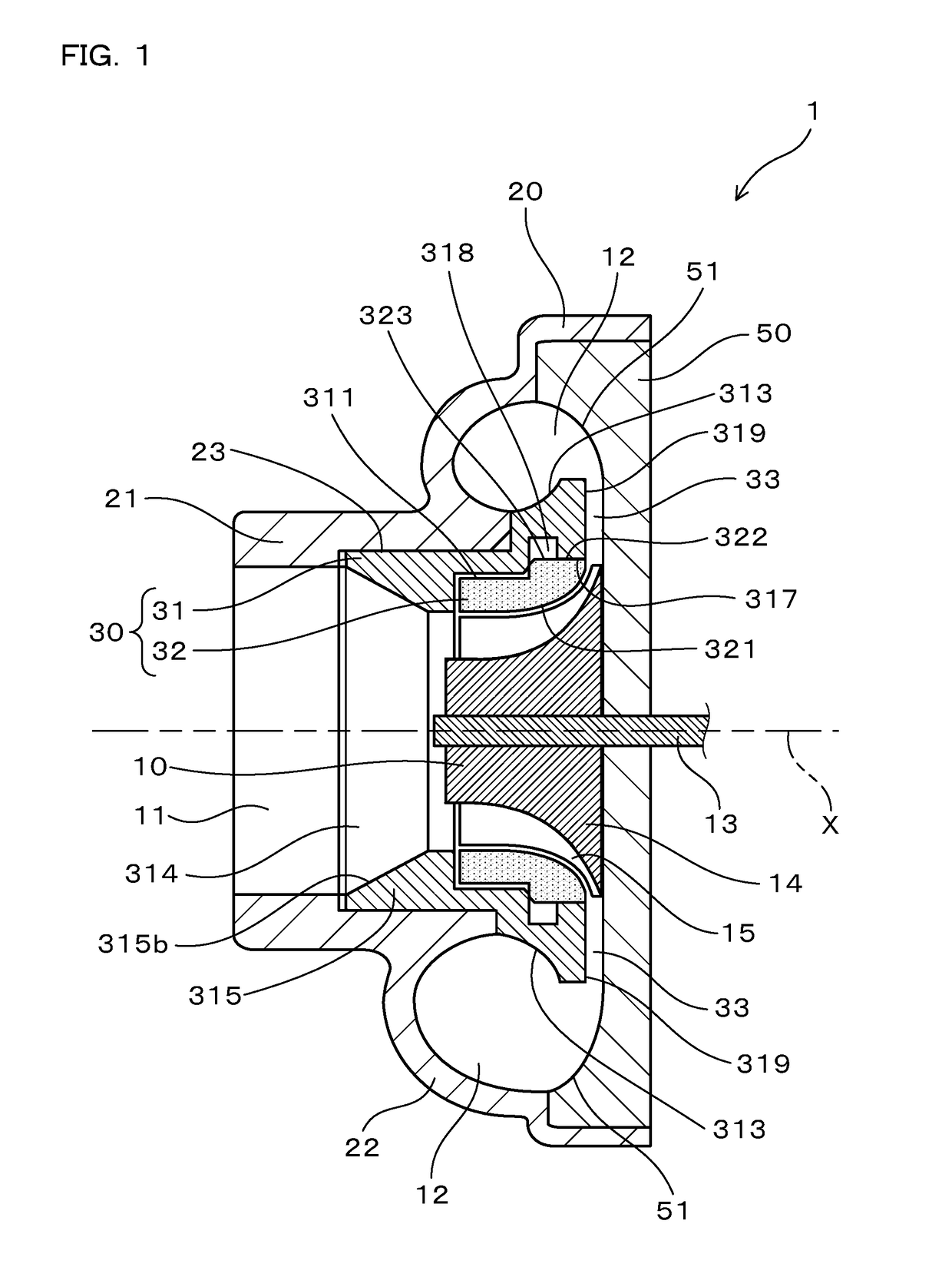
[0050]A compressor housing for a turbocharger according to the present embodiment will be described with reference to FIGS. 1 to 5.

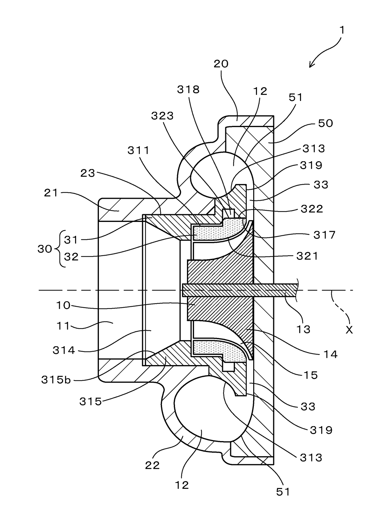
[0051]A compressor housing 1 for a turbocharger according to the present embodiment (hereinafter also referred to as the “compressor housing 1”) is configured to be able to house an impeller 10 and equipped with a scroll unit 20 and a shroud part 30 as shown in FIG. 1.

[0052]The scroll unit 20 includes an intake port 11 for sucking air toward the impeller 10 and a scroll chamber 12 for introducing air discharged by the impeller 10 thereinto. The scroll chamber is formed in a circumferential direction at an outer circumferential side of the impeller 10.

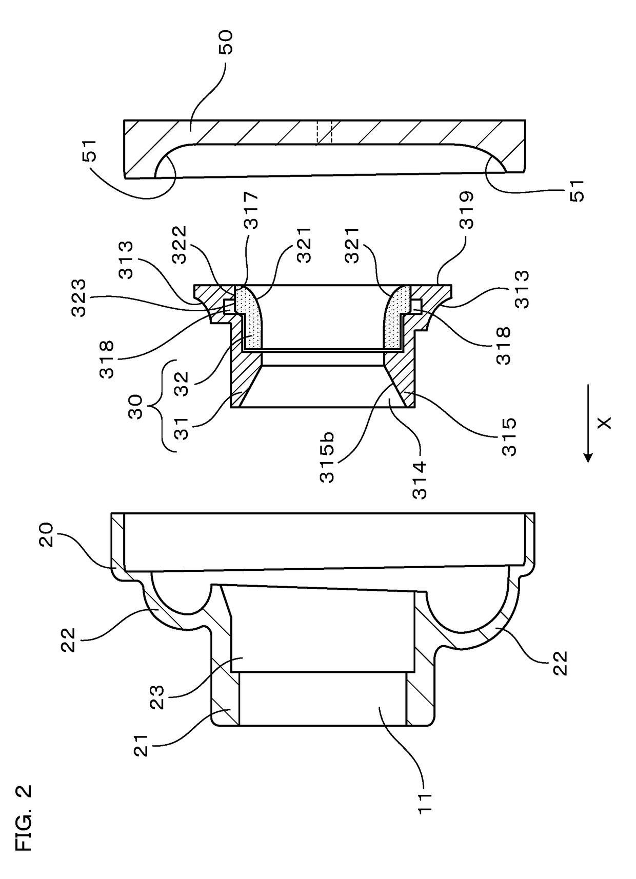
[0053]As shown in FIG. 2, the shroud part 30 is made up of an annular, elastically deformable abradable seal 32, an inner circumferential surface 321 of which serves as the shroud surface 321, and an annular abradable seal fixing part 31 to which the abradable seal 32 is fixed.

[0054]As shown in F...

Example

Embodiment 2

[0096]In the compressor housing 1 according to the present embodiment, as shown in FIG. 7, the abradable seal 32 does not have the cylindrical portion 324 (FIG. 4), and the end portion 323a of the abradable seal 32, positioned forward with respect to the press-fitting direction X abuts against the front-side wall surface 318a of the grooved portion 318 of the abradable seal fixing part 31, positioned forward in the press-fitting direction X. Consequently, the position of the abradable seal 32 in the axial direction X is determined at the end portion 323a positioned forward with respect to the press-fitting direction X. Note that components equivalent to those of Embodiment 1 are denoted by the same reference numerals as the corresponding components, and description thereof will be omitted.

[0097]The present embodiment also achieves operational effects equivalent to those of Embodiment 1 except for the operational effects attributable to the cylindrical portion 324 provide...

Example

Embodiment 3

[0098]In the compressor housing 1 according to the present embodiment, as shown in FIG. 8, the abradable seal 32 has a cut portion 325 formed at a rear end portion of the bulging portion 323, positioned rearward with respect to the press-fitting direction X, (i.e., in a boundary portion between the bulging portion 323 and the press-fit abutting portion 322). As shown in FIG. 8, the cut portion 325 is formed in the circumferential direction along a rear-side wall surface 318b of the grooved portion 318, positioned rearward with respect to the press-fitting direction X. A sectional shape in the axial direction X, of the cut portion 325 is a V-shaped groove and is formed uniformly throughout the circumference. Besides the V-shape, the sectional shape of the cut portion 325 may be a U-shape, rectangular shape, arc shape, or the like. Note that components equivalent to those of Embodiment 1 are denoted by the same reference numerals as the corresponding components, and descri...


PUM


Abstract

A compressor housing for a turbocharger including an intake port, a scroll chamber, and a shroud part. The shroud part includes an annular abradable seal, and an annular abradable seal fixing part. The abradable seal fixing part includes a press-fitting recessed portion into which the abradable seal is press-fitted, and a grooved portion formed at a forward side of the press-fitting recessed portion with respect to a press-fitting direction of the abradable seal. The abradable seal includes a press-fit abutting portion press-fitted into the press-fitting recessed portion, abutting against an inner circumferential surface of the press-fitting recessed portion, and a bulging portion at a forward side of the press-fit abutting portion with respect to the press-fitting direction. The outside diameter of the bulging portion is larger than the inside diameter of the press-fitting recessed portion but smaller than the inside diameter of the grooved portion.

Description

TECHNICAL FIELD[0001]The present invention relates to a compressor housing for a turbocharger.BACKGROUND ART[0002]A compressor for use in a supercharger such as a turbocharger of an automobile includes a compressor housing that is configured to be able to house an impeller, and includes an intake port for sucking air toward the impeller, a scroll chamber for introducing air discharged by the impeller thereinto, the scroll chamber being formed in a circumferential direction at an outer circumferential side of the impeller, and a shroud surface opposed to the impeller.[0003]With the compressor configured as above, compression efficiency of the compressor can be increased by minimizing a gap between blades of the impeller and the shroud surface of the compressor housing.[0004]However, if the gap is decreased, the impeller may be damaged, for example, when the impeller blades come into contact with the shroud surface of the compressor housing due to vibrations, a runout of an impeller r...

Claims


Application Information

Patent Timeline
IPC IPC(8): F04D29/16F02C6/12F04D29/42F04D29/62
CPCF05D2220/40F05D2260/37F01D11/122F04D29/162F02C6/12F04D29/4213F04D29/624F04D29/4206F02C7/00F04D29/62
Inventor MIYOSHI, TOMOKIISOGAI, TOMOYUKIYONEZAWA, KOICHI
Owner OTICS CORP
Why Eureka
Try Eureka