

Endoscope
- Summary
- Abstract
- Description
- Claims
- Application Information
AI Technical Summary
Benefits of technology
Problems solved by technology
Method used
Image

Examples
first embodiment
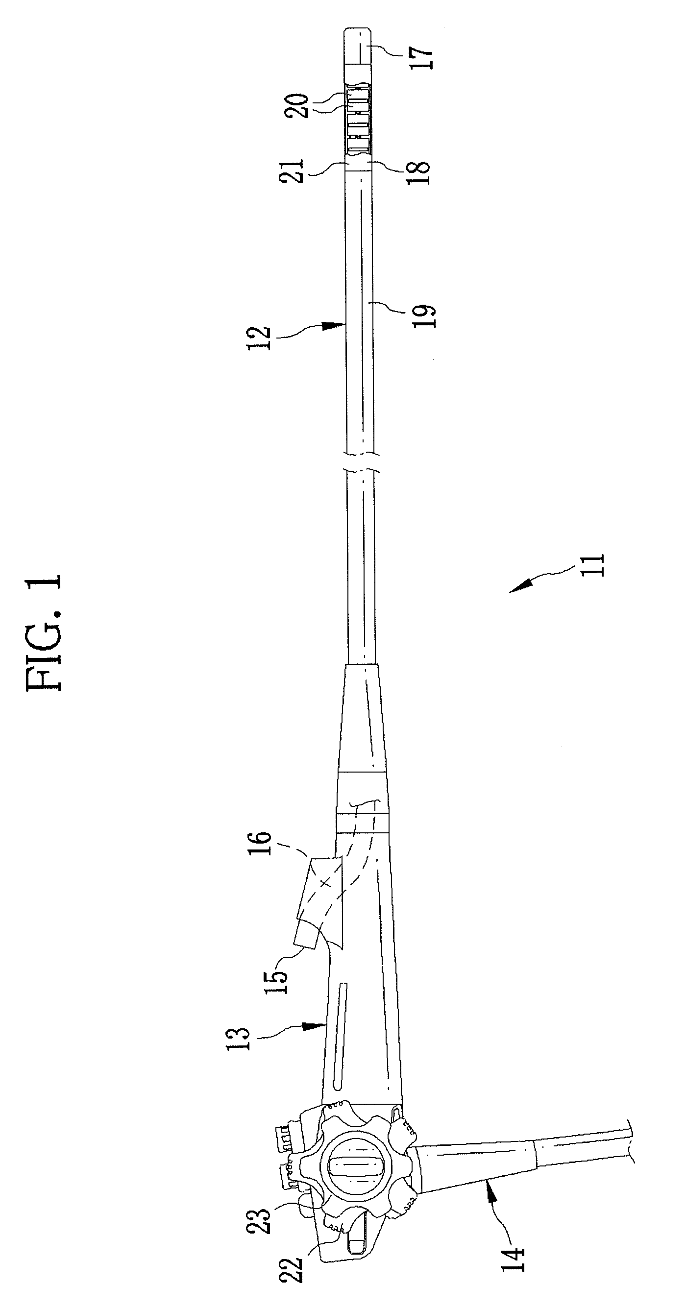
[0033]As shown in FIG. 1, an electronic endoscope (hereinafter referred to as endoscope) 11 is provided with an insertion section 12, an operating section 13, and a universal cord 14. The insertion section 12 is inserted in a body cavity. The operating section 13 is connected to a base end portion of the insertion section 12. The universal cord 14 is connected to the operating section 13. The operating section 13 is provided with a forceps inlet 15 through which a medical instrument (treatment instrument) is inserted. As shown by dashed lines in FIG. 1, the forceps inlet 15 is connected to a forceps channel 16 disposed through the insertion section 12.
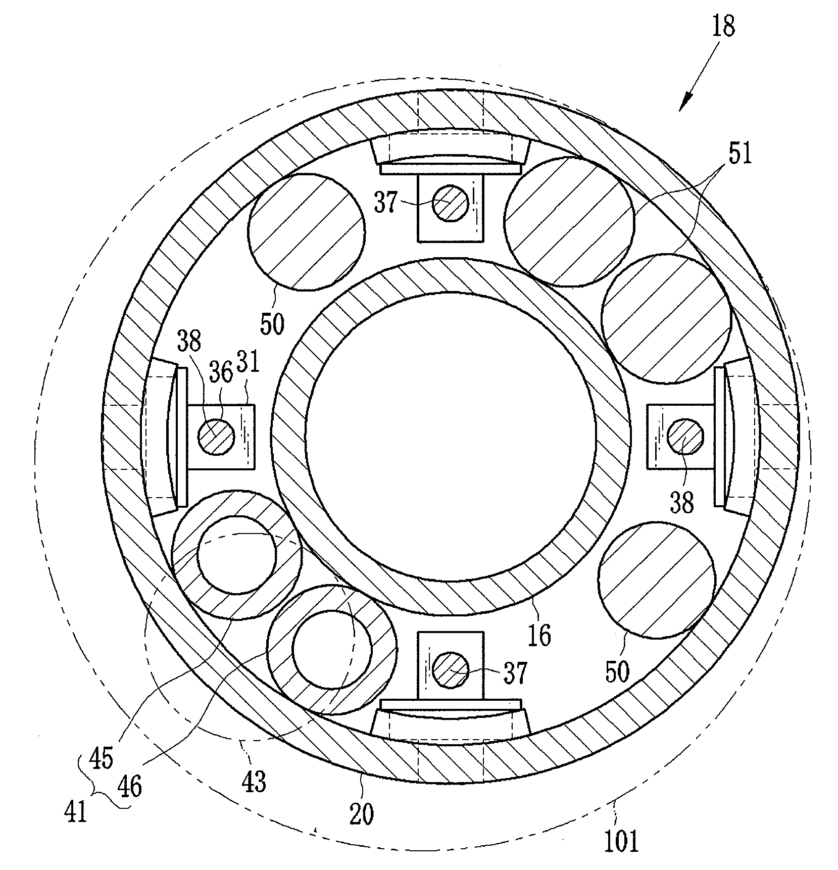
[0034]The insertion section 12 has a rigid portion 17, a bending portion 18, and a flexible portion 19. The rigid portion 17 is provided at a distal tip of the insertion section 12. The bending portion 18 is connected to a base end of the rigid portion 17. The flexible portion 19 is connected to a base end of the bending portion 18.
[00...
second embodiment
[0047]A forceps channel of a nasal endoscope has a smaller diameter than that of an oral endoscope so as to reduce the diameter of the insertion section. Therefore, available medical instruments are limited or only those specifically designed for the nasal endoscopes are used. For this reason, it is demanded to increase the diameter of the forceps channel without increasing the outer diameter of the insertion section. In the above first embodiment, the branch channels 45 and 46 having the small diameters are arranged within the bending portion 18 as the air / water channel 41 to create a space, and the diameter of the insertion section 12 is reduced by eliminating the created space. Alternatively, the diameter of the forceps channel may be increased by utilizing the created space.
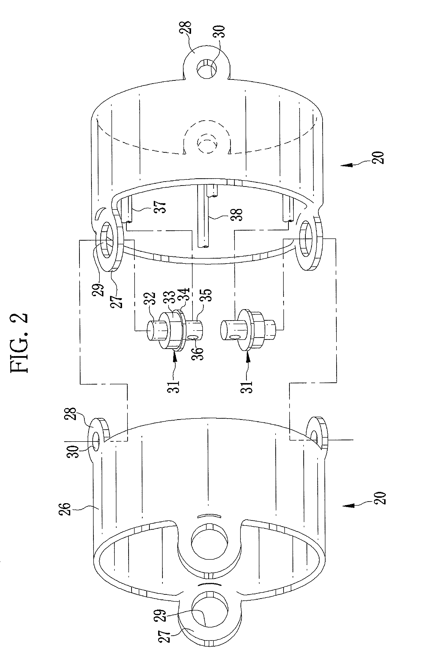
[0048]In the second embodiment, as shown in FIG. 5, joint rings 54 are used instead of the joint rings 20 (see FIGS. 2 and 4) to constitute the bending portion 18. The joint rings 54 have the same configurati...
third embodiment
[0052]In the above embodiments, outer shapes of the branch channels 45 and 46 of the air / water channel 41 have circular cross-sections vertical to axis directions of the branch channels 45 and 46, respectively. However, the cross-sections may be ellipsoidal or flat-shaped. In this case, the inner shape of the branch channels 45 and 46 is circular in cross-section vertical to the axis directions thereof, respectively. In the above embodiments, the optical fibers 50 and the signal line 51 have circular cross-sections vertical to the axis directions of the optical fibers 50 and the signal line 51, respectively. Alternatively, at least one of the optical fibers 50 and the signal line 51 may have an ellipsoidal or a flat-shaped outer shape in cross-section vertical to its axis direction, at least within the bending portion 18. The optical fibers 50 and the signal line 51 are covered with tubes, respectively. The inner shapes of the tubes are circular in cross-sections vertical to the axi...
PUM
 Abstract
Description
Claims
Application Information