Clip on doorstop

a technology for doors and clips, applied in the field of doorstops, can solve the problems of not being portable enough to move, leaving behind holes or other damage in the doors on the doortop, and a higher probability of mechanical failure, so as to achieve greater protection against chaffing damage

Active Publication Date: 2014-01-02
MULLENBACH ALAN
View PDF1 Cites 8 Cited by
  • Summary
  • Abstract
  • Description
  • Claims
  • Application Information

AI Technical Summary

Benefits of technology

[0007]A further object of the invention is to provide a portable doorstop that does not damage the surface on which it is mounted. The portable door clip may employ a coating of Teflo

Problems solved by technology

Due to their mounting hardware, they tend to be permanently affixed to one door and not portable enough to move to other doors that require a doorstop.
If they are removed, they leave behind holes or other damage in the doors they were mounted to.
The design in U.S. Pat. No. 2,774,622 and U.S. Pat. No.5,542,725 accommodate varying door thickness, however they contain a multitude of

Method used


Image

  • Clip on doorstop
  • Clip on doorstop
  • Clip on doorstop

Examples


Embodiment Construction

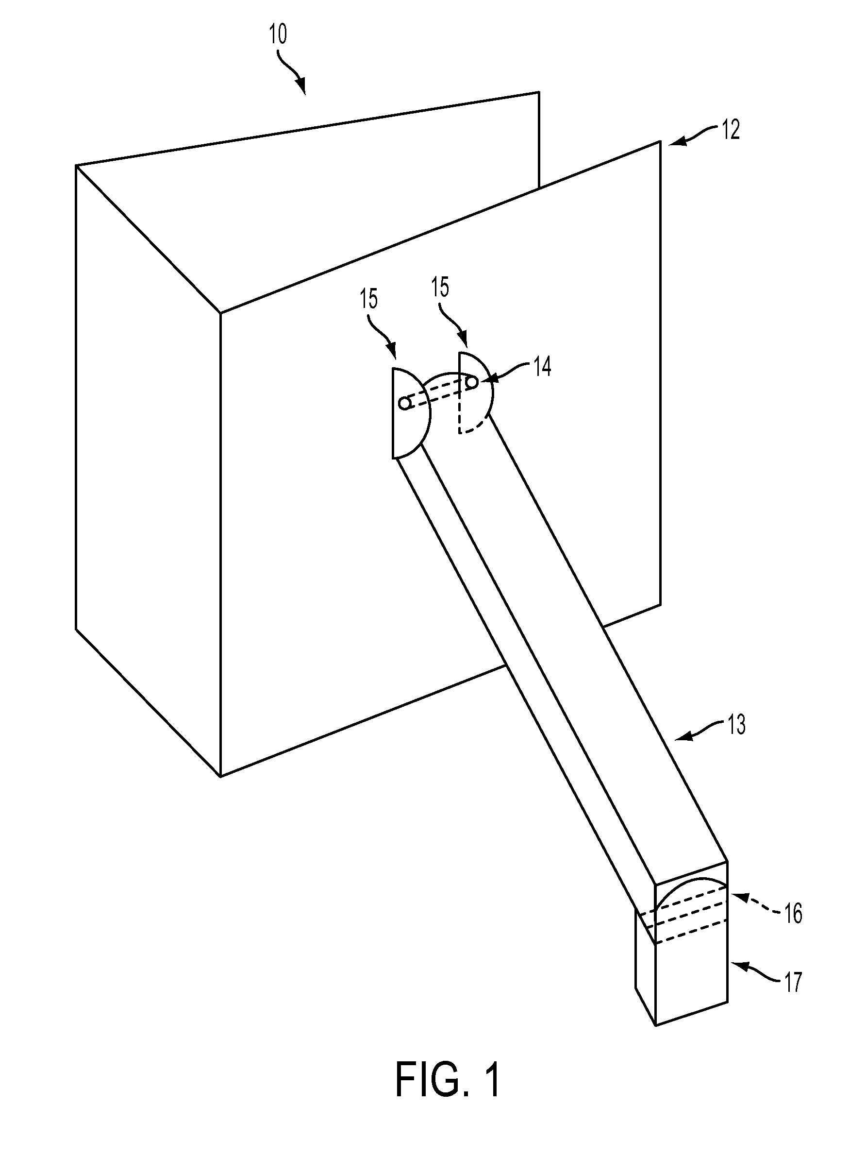
[0018]Referring to FIGS. 1, 4 and 5 a door stop assembly 10 employs a portable door clip 12. The portable door clip 12 comprises sequence of three sides which may be obtained by folding a single piece of flat planar material such as spring steel or other suitable flexible material. One of ordinary skill in the art will understand there are a number of alternative ways to either fold or attach the three sides such as welding, or various adjoining hardware. As displayed in FIGS. 3b and 3c, the three sides of the portable door clip 12 comprise a first front side which is intended to abut the planar side of a swing door 23, a second side positioned at a right or acute angle to the first side which is intended to abut the jamb side of the door 23, and a third back side positioned at a substantially acute angle to the second side which is intended to abut the opposite planar side of the door 23 as the first front side. Because of its flexibility, angle pattern, and the surface area of its...


PUM


Abstract

Disclosed is a doorstop assembly which allows a doorstop to be conveniently installed or removed from left or right swinging doors of varying thicknesses. The assembly has a portable door clip which may be easily pulled off a left swing door, turned upside down, and then pushed into place onto a right swing door. The portable door clip can firmly embrace doors of varying thickness. A dual lock leg mounted to the front of the door clip can be stowed in an upward position regardless of which way the door clip is turned, and then lowered toward the floor surface when in use to stop the door from closing.

Description

FIELD OF THE INVENTION[0001]The present invention relates to doorstops, and more particularly, to a Portable clip on doorstop assembly that mounts onto standard swing type doors.BACKGROUND OF THE INVENTION[0002]Standard type mounted doorstops are known in the art. They are typically mounted to the surface of a door with various types of mounting hardware. When the door is opened, the doorstop leg is moved from an upward stowed position to a downward position where it engages the floor and holds the door in place as shown in U.S. Pat. No. 3,831,989. Due to their mounting hardware, they tend to be permanently affixed to one door and not portable enough to move to other doors that require a doorstop. If they are removed, they leave behind holes or other damage in the doors they were mounted to.[0003]To address the problem of portability, doorstop assemblies such as shown in U.S. Pat. No. 2,709,615 , U.S. Pat. No. 5,542,725 , and U.S. Pat. No. 2,774,622 were made. These door stop assemb...

Claims


Application Information

Patent Timeline
IPC IPC(8): E05C19/18
CPCE05C19/188E05C17/443E05C17/54Y10T292/34
Inventor MULLENBACH, ALAN
Owner MULLENBACH ALAN
Why Eureka
Try Eureka