Modified retrofocus-type wide-angle lens

Active Publication Date: 2014-01-02
LEICA GEOSYSTEMS AG
View PDF0 Cites 6 Cited by
  • Summary
  • Abstract
  • Description
  • Claims
  • Application Information

AI Technical Summary

Benefits of technology

The invention aims to remove or reduce as much as possible the field curvature and transverse chromatic aberration in retrofocus-type lenses. This will reduce the likelihood of large aberrations and improve the quality of imaging during focusing.

Problems solved by technology

The correction state of the lens in the near-field range is therefore unsatisfactory.
A further problem of these lenses is that the focusing paths are often unsuitable for fast focusing, as is required for e.g. autofocusing purposes.

Method used


Image

  • Modified retrofocus-type wide-angle lens
  • Modified retrofocus-type wide-angle lens
  • Modified retrofocus-type wide-angle lens

Examples


Embodiment Construction

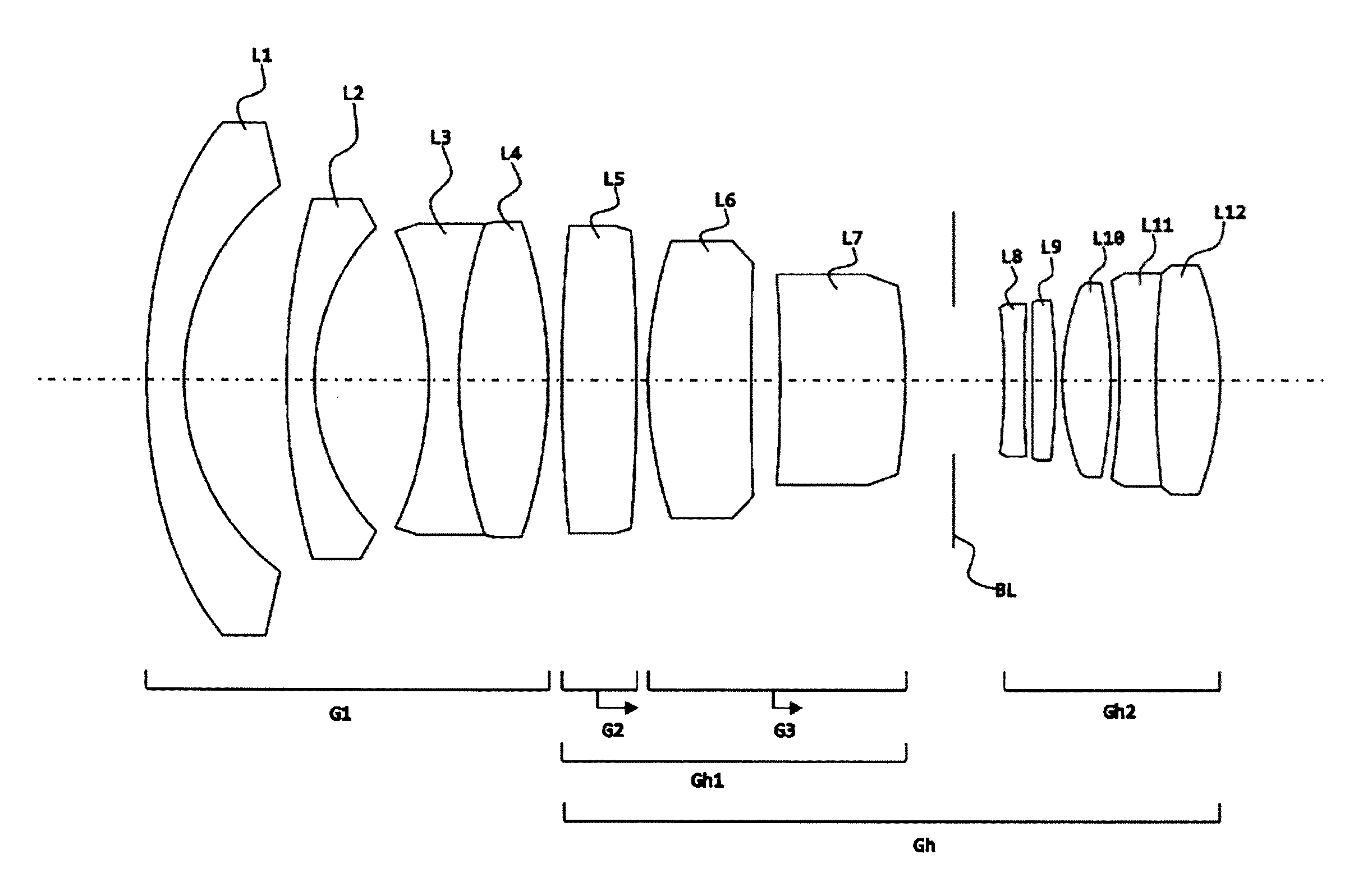
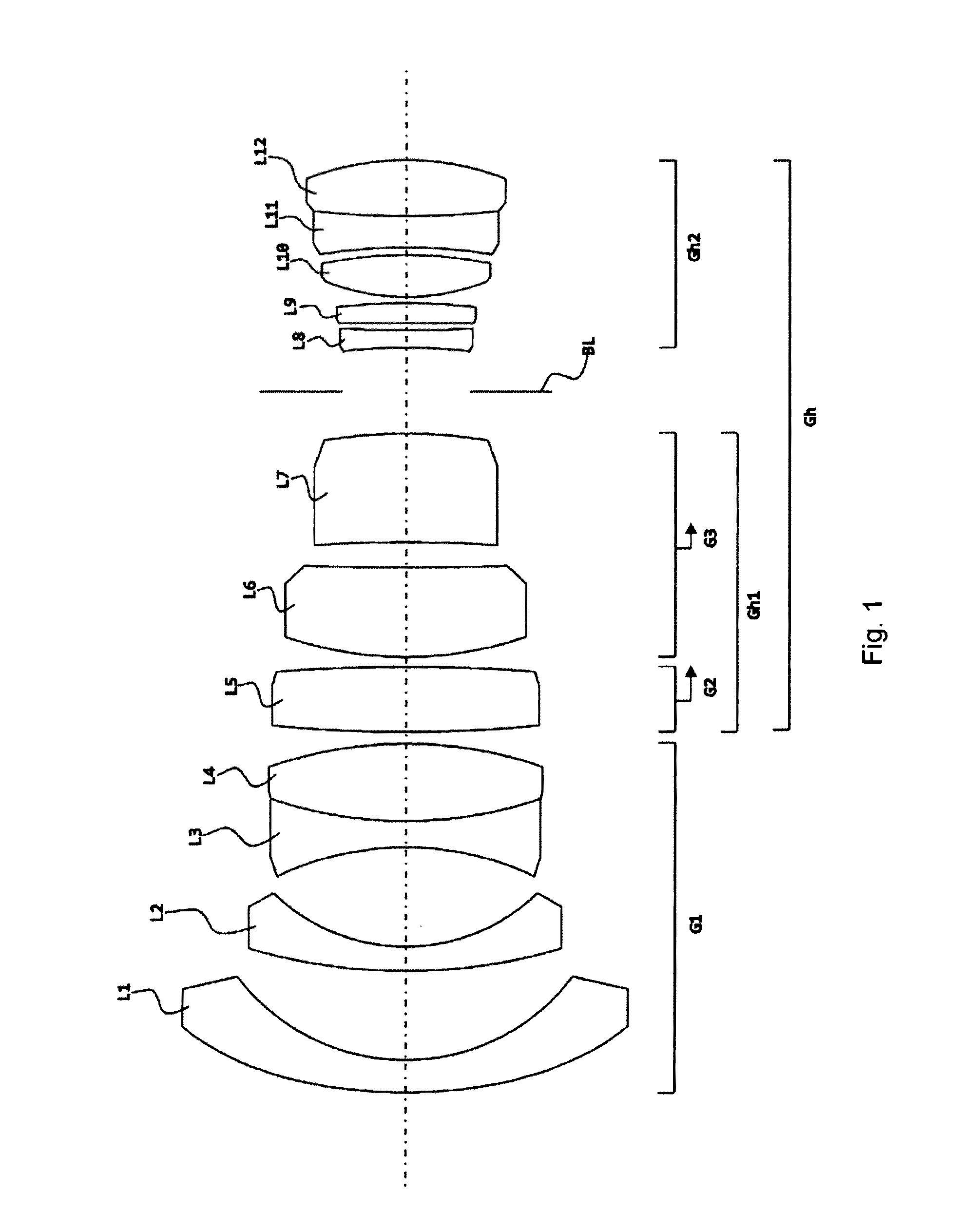
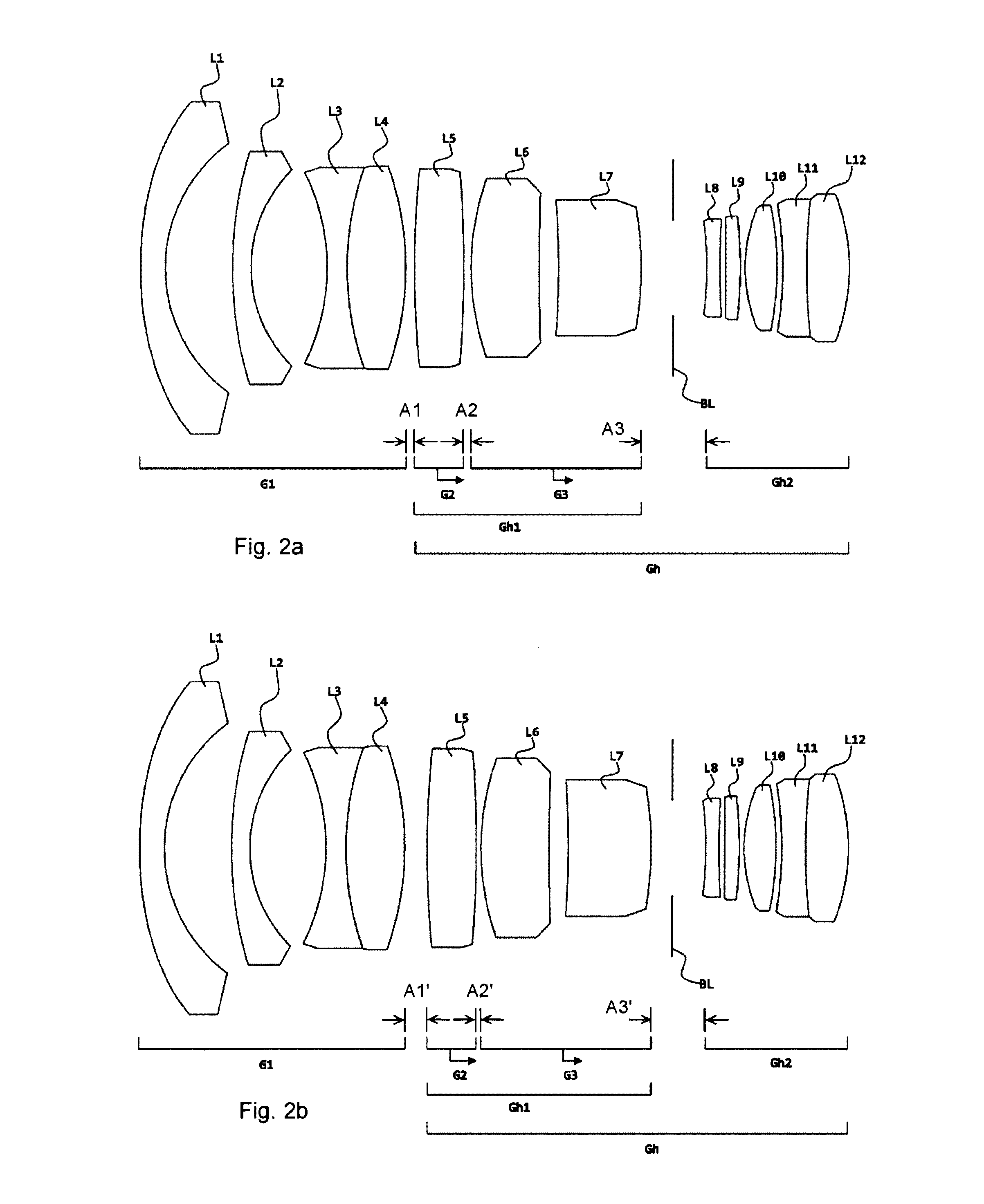
[0017]FIG. 1 illustrates the subdivision of the lens, as seen in the light direction, into a front lens group (G1) with negative refractive power and a rear group (Gh) with positive refractive power, which is associated with an image plane (not illustrated in any more detail). The rear group (Gh) has a first rear group (Gh1) with positive refractive power, displaceable along the optical axis (illustrated by a dashed line) for focusing purposes, and a second rear group (Gh2) with positive refractive power facing the image plane. The distance between the front group (G1) and the second rear group (Gh2) remains constant during focusing. An aperture stop (BL) is arranged in a stationary fashion between the first rear group (Gh1) and the second rear group (Gh2). According to embodiments of the invention, the first rear group (Gh1) consists of two lens unit groups (G2, G3) with positive refractive power and is displaceably mounted in the direction of the second rear group (Gh2) or the ape...


PUM


Abstract

What is described is a modified retrofocus-type wide-angle lens, with, as seen from the object, a front group (G1) with negative refractive power, a first rear group (Gh1) with positive refractive power displaceable along the optical axis for focusing purposes and a second rear group (Gh2) with positive refractive power facing an image plane.

Description

CROSS-REFERENCE TO RELATED PATENT APPLICATIONS[0001]The right of foreign priority is claimed under 35 U.S.C. §119(a) based on Federal Republic of Germany Application No. 10 2012 105 707.9, filed Jun. 28, 2012, the entire contents of which, including the specification, drawings, claims and abstract, are incorporated herein by reference.BACKGROUND OF THE INVENTION[0002]The invention relates to a photographic modified retrofocus-type wide-angle lens.[0003]U.S. Pat. No. 5,909,319 A has disclosed a lens in which the overall length does not change over the whole focusing path. As seen from the object side, the lens has, in the light direction, a first lens unit group with overall positive refractive power which contains a negative lens unit. The second and third lens unit groups, as seen in the light direction, each consist of a cemented element with negative refractive power and the fourth lens unit group has positive refractive power. The lens elements two and three are displaceably mou...

Claims


Application Information

Patent Timeline
IPC IPC(8): G02B13/04
CPCG02B13/04
Inventor ROTH, STEFANKARBE, PETER
Owner LEICA GEOSYSTEMS AG
Why Eureka
Try Eureka