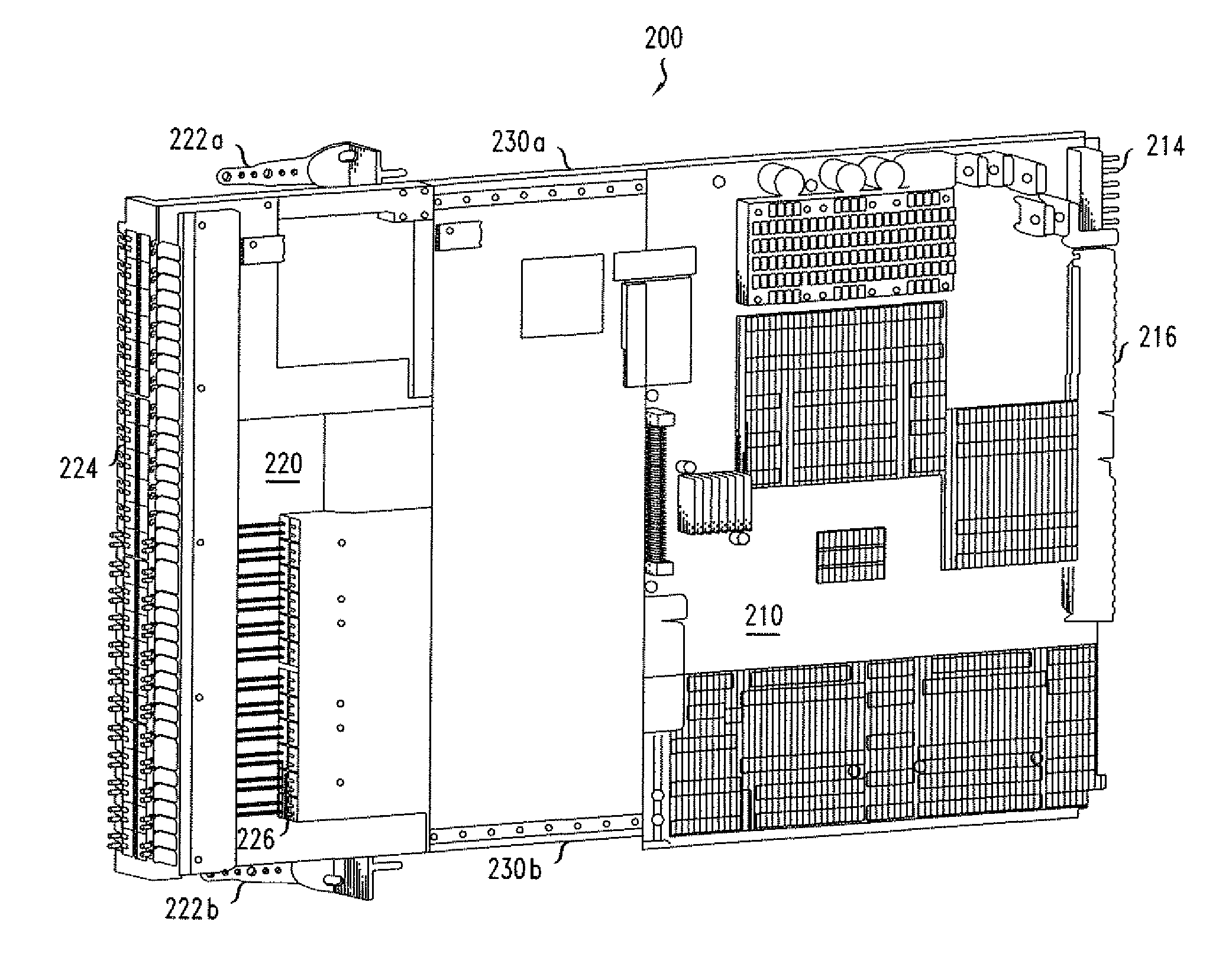
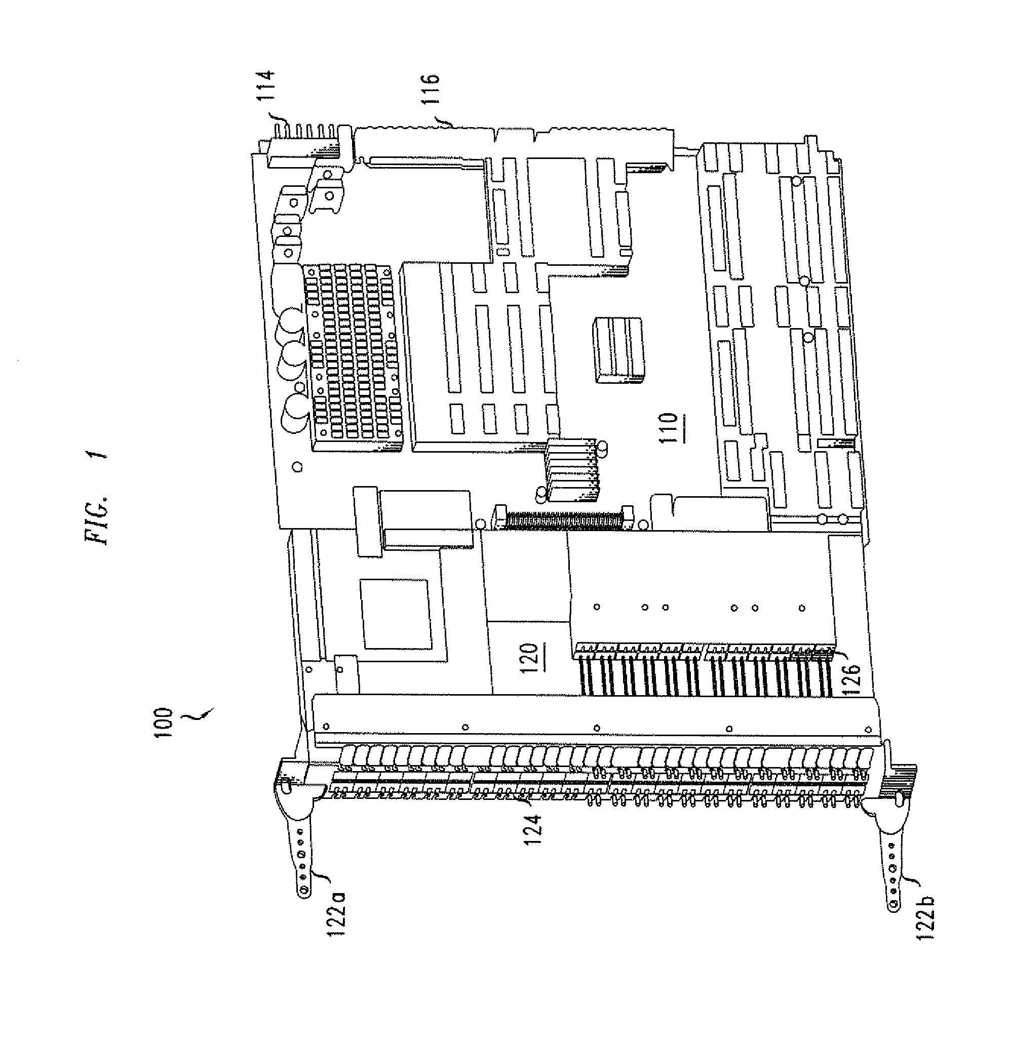
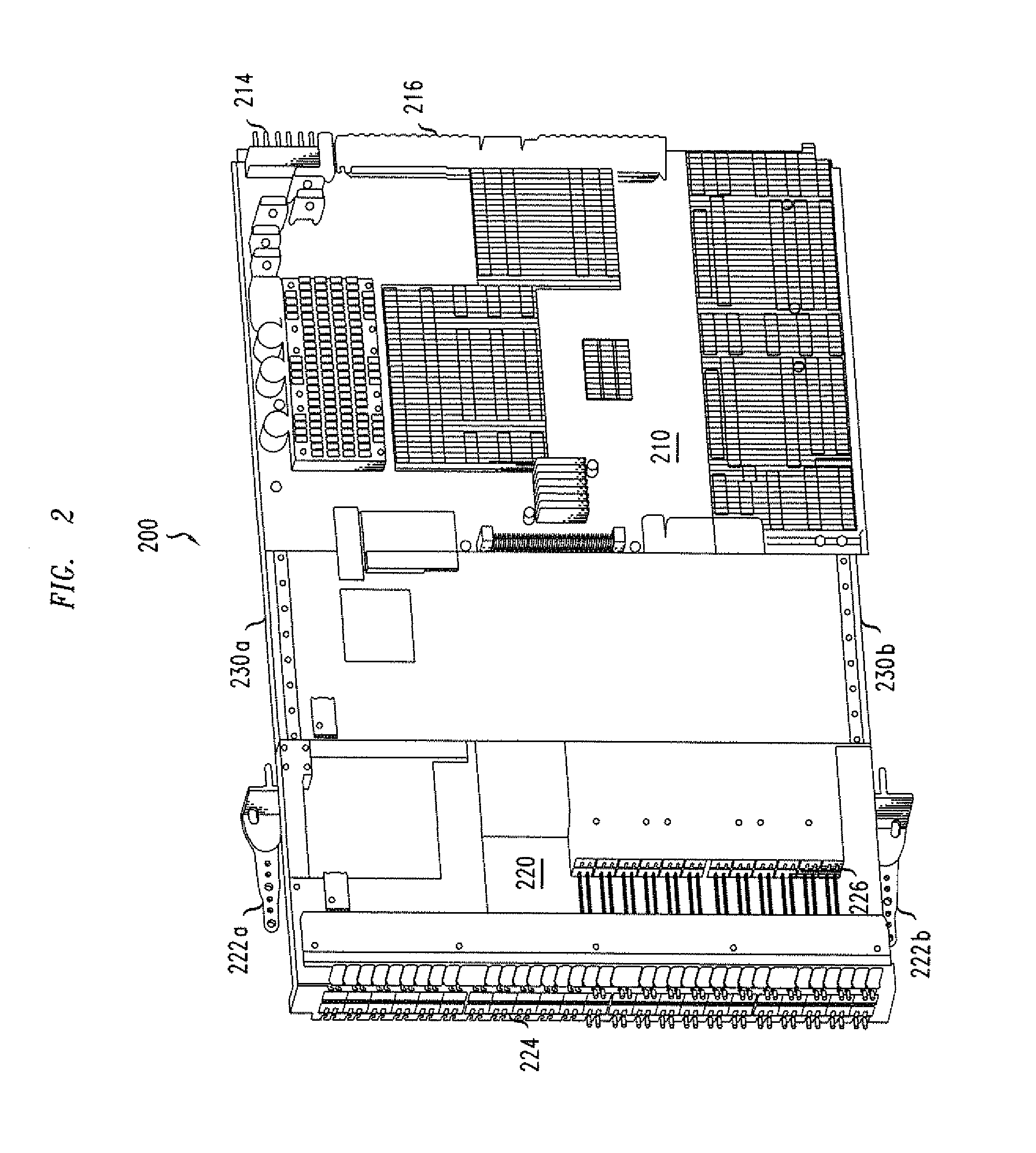
Increased connector port density via extending faceplate

a technology of connector port and faceplate, which is applied in the direction of instrumentation, coupling device connection, support structure mounting, etc., can solve the problems of limited quantity of such components, limited attempts to increase the density of connector port by decreasing the size of pluggable media, and limited attempts to increase the faceplate area, so as to achieve the effect of increasing the density of connector por

Inactive Publication Date: 2014-01-02
RPX CORP
View PDF14 Cites 1 Cited by
  • Summary
  • Abstract
  • Description
  • Claims
  • Application Information

AI Technical Summary

Benefits of technology

[0007]It is an object of the invention to provide a method and apparatus for increasing the connector port density available to a printed circuit board assembly in a shelf with a given height and assembly spacing.

Problems solved by technology

As may be apparent, the quantity of such components is limited by the mounting area provided by the faceplate.
Attempts to increase connector density by decreasing the size of the pluggable media are limited by standard form factors for commonly used media, whereas attempts to increase the faceplate area are limited by the shelf height and given printed circuit board assembly spacing across the shelf.

Method used


Image

  • Increased connector port density via extending faceplate
  • Increased connector port density via extending faceplate
  • Increased connector port density via extending faceplate

Examples


Embodiment Construction

[0024]In the following description, numerous specific details are set forth. However, it is understood that embodiments of the invention may be practiced without these specific details. In other instances, well-known circuits, structures and techniques have not been shown in detail in order not to obscure the understanding of this description. It will be appreciated, however, by one skilled in the art that the invention may be practiced without such specific details. Those of ordinary skill in the art, with the included descriptions, will be able to implement appropriate functionality without undue experimentation.

[0025]References in the specification to “one embodiment”, “an embodiment”, “an example embodiment”, etc., indicate that the embodiment described may include a particular feature, structure, or characteristic, but every embodiment may not necessarily include the particular feature, structure, or characteristic. Moreover, such phrases are not necessarily referring to the sa...


PUM


Abstract

An increased connector port density assembly is disclosed for providing more connector ports than would normally fit on a faceplate. The increased connector port density assembly includes a stationary board and an extendable board connected to the stationary board on rails and with cabling. The extendable board has a first and second set of forward facing connector assemblies. The first set accessible when the extendable board is in either the retracted or extended position, whereas the second set of connector assemblies is accessible when the extendable board is in the extended position. The increased connector port density assembly is particularly useful for overcoming faceplate connector area availability limitations known in the art.

Description

FIELD OF THE INVENTION[0001]The invention relates to generally to providing increased connector port density and is particularly concerned with providing more connector ports than may mechanically reside on the faceplate of a circuit card.BACKGROUND OF THE INVENTION[0002]The use of printed circuit board assemblies mounted in shelves is well known in electronic systems. Typically these printed circuit board assemblies are oriented vertically and disposed adjacent to each other across the width of the shelf. The vertical disposition facilitates cooling via air flow, either convective or forced, and facilitates access to the separate assemblies independent of each other.[0003]These assemblies typically comprise printed circuit boards with interconnecting conductive traces for components mounted thereon, and a connector for connection to a backplane or midplane. The components and their compatible connectors are typically electronic and optical in nature. These printed circuit board ass...

Claims


Application Information

Patent Timeline
Patent Type & Authority Applications(United States)
IPC IPC(8): H01R13/44G02B6/36
CPCG02B6/3817G02B6/3897H04Q1/023H04Q1/14H05K7/1461
Inventor SCHRIEL, JAMES MICHAELLABIB, RAMI
Owner RPX CORP
Why Eureka
Try Eureka