Method and system for waking up remote devices

a remote device and system technology, applied in power management, high-level techniques, instruments, etc., can solve the problems of high cost, high power consumption, complex system structure, etc., and achieve the effect of wide applicability and easy implementation

Inactive Publication Date: 2015-06-16
NANJING UNIV
View PDF6 Cites 1 Cited by
  • Summary
  • Abstract
  • Description
  • Claims
  • Application Information

AI Technical Summary

Benefits of technology

[0051]If a conventional 90V ringing wake-up approach is used, ringing power higher than 1 W has to be provided by the office side during the ringing period. For the central office equipment that has high port density, both the power consumption and the heat dissipation are challenges; as a result, further improvement of integration level is restricted. However, with the remote wake-up method according to the present invention, the required power is no more than several milliwatts; therefore, the difficulties in power consumption and thermal design of the central office equipment are greatly reduced, without impacting the original waking-up capability. Thus, the method provided in the present invention meets the trend of low carbon economy.
[0053]With the technical scheme of the present invention, the ringing generator module that generates voltage as high as 90V AC is completely omitted, the maximum operating voltage of the entire system is decreased to the DC voltage rating required for normal operation of the system, and the requirement for safety protection against electric leakage and electric shock and requirement for voltage withstand process of the system are greatly lowered; therefore, the system can be applied more widely and the integration level of the system itself can be further improved.
[0055]An embodiment of the present invention can wake up the remote device by generating and identifying a reversed polarity voltage signal. The remote device can be in complete power-off state: when the remote device is to be waken up, the wake-up signal is only to be rectified so as to obtain the power required for waking up the power supply module, and the power supply can also be provided with the wake-up signal voltage. In that way, the phenomenon that the signaling-based waking-up method for waking up network card and modem, which both required the equipment provides maintain power with certain power, is avoided.
[0057]The methods for generation and identification reversed polarity voltage signal disclosed in the present invention are simple. An embodiment for generating a wake-up signal only requires a DPDT switch; an embodiment for identifying the wake-up signal only requires a diode; both the embodiments are easy to implement. The entire waking-up system simply comprises a wake-up signal generator unit, a remote device power supply unit, and a wake-up signal feeding line and does not involve any special application of remote device. Therefore, the method and system disclosed in the present invention are applicable to almost all cases in which remote wake-up function is required and cable connection is available. That is to say, the method and system disclosed in the present invention have wide applicability.

Problems solved by technology

The above waking up method used in simulation telephone system requires a separate ringing generator unit; in addition, there is a confliction between the simulation telephone system and the current detection system of on / off-hook state, and the structure of the system is very complex.
Moreover, the 90V AC ringing approach results in high power consumption and high cost, which do not meet the demand for energy conservation and environmental protection; therefore, that approach should be abandoned.
However, the waking-up and calling approach of ordinary telephone sets is only suitable for manual operation, but is not suitable for DSL modem's operate mode.
If two units actively start up into operating state at the same time on a telephone line, or they start up into operating state because they receive calling signals at the same time, usually the DSL modem cannot establish a normal connection.
At present, these devices have to be started up manually or always kept in ON state, and cannot realize remote waking up.

Method used


Image

  • Method and system for waking up remote devices
  • Method and system for waking up remote devices
  • Method and system for waking up remote devices

Examples


embodiment 1

[0093]This embodiment provides remote waking-up system and method that utilize reversed polarity DC voltage as the wake-up signal.

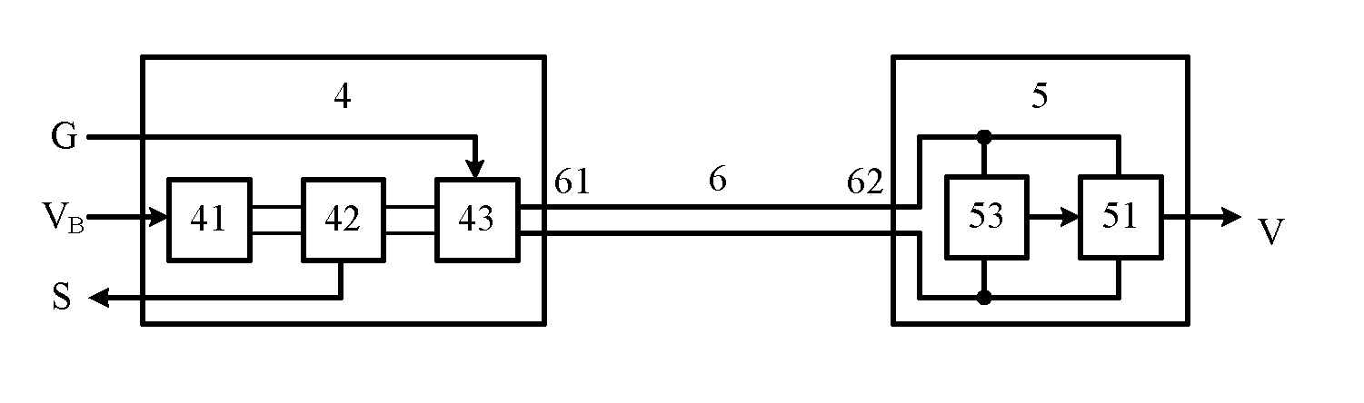
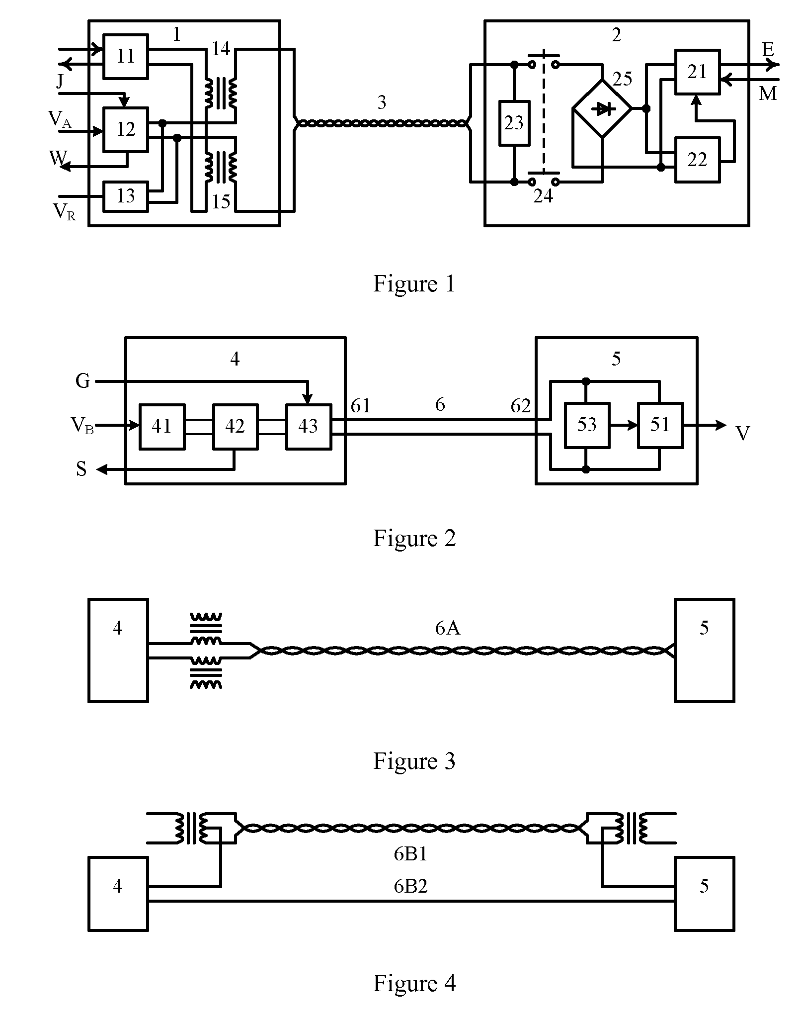
[0094]In this embodiment, the remote waking-up system comprises: a wake-up signal generator unit 4, a remote device power supply unit 5, and a wake-up signal feeding line 6 that connects the wake-up signal generator unit 4 and the remote device power supply unit 5.

[0095]The wake-up signal generator unit 4 is designed to generate voltage signals with different characteristics, including wake-up signal, normal state signal, and occupation signal, and send the voltage signals to the remote device power supply unit 5 through the wake-up signal feeding line 6.

[0096]The remote device power supply unit 5 is designed to be waken up remotely from sleep state and generate local power supply output, and feed back a remote device power supply state signal to the wake-up signal generator unit 4 through the wake-up signal feeding line 6.

[0097]In addition, the wake-up s...

embodiment 2

[0147]This embodiment provides remote waking-up system and method that utilize DC voltage pulse codes with different polarities as wake-up signals.

[0148]In this embodiment, as shown in FIG. 17, the remote waking-up system comprises: a wake-up signal generator unit 4A, remote device power supply units 5A, and a wake-up signal feeding line 6 that connects the wake-up signal generator unit 4A and remote device power supply units 5A. The wake-up signal generator unit 4A comprises: a power supply input port VB, a wake-up control port G, a remote device state output port S, a feeding line output port 61, a power supply module 41, a current detection module 42, and a wake-up signal generator module 43A. The remote device power supply unit 5A comprises: a wake-up feeding line port 62, a wake-up signal detection module 53A, a controllable power supply module 51, and a supply voltage output port V.

[0149]Said wake-up signal generator module 43A outputs a DC voltage pulse code with polarity rev...

embodiment 3

[0183]This embodiment provides remote waking-up system and method that utilize voltage with different amplitude as the wake-up signal.

[0184]In this embodiment, as shown in FIG. 20, the remote waking-up system comprises: a wake-up signal generator unit 4B, a remote device power supply unit 5B, and a wake-up signal feeding line 6 that connects the wake-up signal generator unit 4B and the remote device power supply unit 5B. The wake-up signal generator unit 4B comprises: a power supply input port VB, a wake-up control port G, a remote device state output port S, a feeding line output port 61, a power supply module 41, a current detection module 42, and a wake-up signal generator module 43B. The remote device power supply unit 5B comprises: a wake-up feeding line port 62, a wake-up signal detection module 53B, a controllable power supply module 51, and a supply voltage output port V.

[0185]Said wake-up signal generator module 43B outputs a voltage wake-up signal with amplitude different ...


PUM


Abstract

Disclosed are a method and a system for remote wake-up and status check, with a wake-up signal generating unit generating and transmitting a wake-up signal to wake up an electricity supply unit of a remote device to operate normally and provide electricity for the remote device. The wake-up signal has an assigned electric voltage with specific characteristics for detection by the electricity supply unit while in power-off mode and, upon signal detection, the electricity supply unit wakes up to provide normal electric voltage output. The wake-up signal generating unit determines, according to an electric current on a wake-up signal feed line, whether the remote device is in an active mode. A low wake-up energy consumption enables system wake-up and a true powered-off sleep mode.

Description

FIELD OF THE INVENTION[0001]The present invention pertains to a method and a system for controlling the power consumption of remote devices, in particular a method and a system for waking up remote devices through cable lines.BACKGROUND OF THE INVENTION[0002]Ordinary fixed telephone systems have remote waking-up and state detection capability, i.e., the central office equipment can remote wake up terminal units and detect the state of terminal units through twisted pair lines.[0003]FIG. 1 shows a block diagram of the subscriber network interface part of an ordinary telephone system, comprising a central office interface equipment 1, a telephone set 2, and twisted pair lines 3 that connect the central office interface equipment 1 and telephone set 2, wherein, the central office interface equipment 1 further comprises a voice receiving / transmitting module 11, a power supply and monitoring module 12, a ringing generator module 13, and transformers 14 and 15; the telephone set comprises...

Claims


Application Information

Patent Timeline
Patent Type & Authority Patents(United States)
IPC IPC(8): G06F1/32H04M1/738H04W52/02
CPCG06F1/3234H04M1/738H04W52/0229Y02D30/70
Inventor CHEN, XIANGNINGZHANG, JIEHAO, LIFANG
Owner NANJING UNIV
Why Eureka
Try Eureka