
A manufacturing method of through-silicon via device applied to high-speed broadband optical interconnect and device thereof

A manufacturing method and broadband optical technology, applied in the field of microelectronics, can solve problems such as inappropriateness, increased cost and power consumption, and difficult application, and achieve the effects of increasing port density, improving integration density, and reducing module size

Active Publication Date: 2016-06-15
NAT CENT FOR ADVANCED PACKAGING
View PDF12 Cites 2 Cited by
  • Summary
  • Abstract
  • Description
  • Claims
  • Application Information

AI Technical Summary

Problems solved by technology

The development trend of the mismatch between the two in terms of process nodes determines that it is obviously inappropriate to use the same CMOS process to complete the optical and electrical parts, and it is not the best choice in terms of cost control.
Although the wirebonding method is easy to assemble, due to loss and other issues, RC delay and inductance effect are obvious in high-frequency and high-speed systems. These defects limit its application. It is necessary to shorten the length of the wirebonding gold wire as much as possible to reduce loss. In the next hundred years In Gigabit Ethernet or even Tbit transmission systems, it is almost difficult to apply
The Flip-Chip method can avoid the loss of gold wires to a large extent because of the direct interconnection method. However, with the continuous reduction of the process node of the COMS chip, it is more difficult to continue to reduce the circuit line width and spacing of the PCB version. The current technology level is still at the micron level. If you want to assemble the electronic chip that is already a package on the PCB substrate, it will obviously increase the cost and power consumption, and it is not conducive to compact and miniaturized integration.
[0005] For the coplanar assembly of discrete patches of photonic devices and electronic devices, a problem that must be considered is the allocation of patch space. It is required that not only the coupling form of the light source and the corresponding space be reserved at the beginning of the design of the photonic integrated chip In addition, it is necessary to reserve a suitable space for the electrical chip, which increases the design cost of the designer and is not conducive to the optimal design of photonic integration.

Method used


Image

  • A manufacturing method of through-silicon via device applied to high-speed broadband optical interconnect and device thereof
  • A manufacturing method of through-silicon via device applied to high-speed broadband optical interconnect and device thereof
  • A manufacturing method of through-silicon via device applied to high-speed broadband optical interconnect and device thereof

Examples


Embodiment Construction

[0030] In order to make the above objects, features and advantages of the present invention more comprehensible, specific implementations of the present invention will be described in detail below in conjunction with the accompanying drawings.

[0031]In the following description, a lot of specific details are set forth in order to fully understand the present invention, but the present invention can also be implemented in other ways different from those described here, and those skilled in the art can do without departing from the connotation of the present invention. By analogy, the present invention is therefore not limited to the specific examples disclosed below.

[0032] Secondly, the present invention is described in detail in combination with schematic diagrams. When describing the embodiments of the present invention in detail, for the convenience of explanation, the cross-sectional view showing the device structure will not be partially enlarged according to the gener...


PUM


Abstract

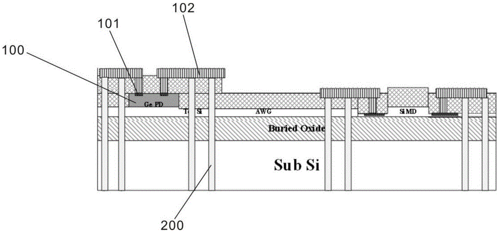
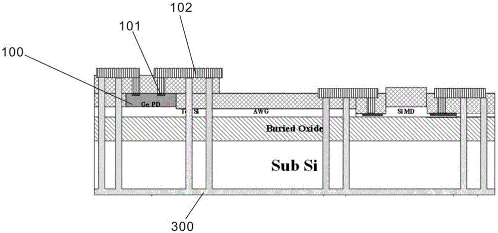
The invention discloses a manufacturing method applied to a high-speed broadband optical interconnection TSV device and the silicon-based optical interconnection device. According to the method and the silicon-based optical interconnection device, firstly, a wide ring is etched to be filled with insulating material, then, silicon surrounded by the insulating ring is etched to form deep TSVs, and finally, the deep TSVs are filled with metal to be connected with the electrodes of front face photonic devices. Due to formation of the wide ring, the thickness of an insulating layer is increased, meanwhile, filling of the insulating material is facilitated, and therefore the TSV parasitic capacitance is greatly reduced, and transmission of high-speed broadband signals is facilitated; meanwhile, the TSVs are formed after the wide ring is filled with the insulating material, many technological problems caused by the situation that in a traditional technology, the insulating material at the bottoms of the TSVs is first selectively etched when the TSVs are metallized are avoided, and the silicon-based optical interconnection device can be connected to the electrodes of the wafer front face photonic devices from the back face more easily. According to the method and the silicon-based optical interconnection device, CMOS devices are integrated on the back face, the Si photonic devices are integrated on the front face, higher freedom degree can be provided for photonic monolithic integration design, and it is also guaranteed that more light source coupling modes can be selected in future.

Description

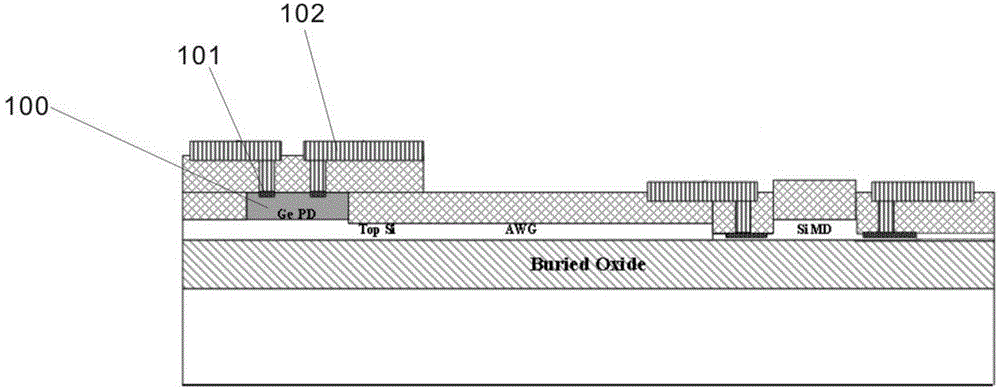
technical field [0001] The invention relates to the technical field of microelectronics, in particular to a method for manufacturing through-silicon hole devices applied to high-speed broadband optical interconnection and devices thereof. Background technique [0002] In the photoelectric module, it mainly includes two parts: the optical part chip and the matching and control circuit. Among them, photonic chips mainly include active and passive types. Active ones mainly include photoelectric modulators (modulators), photodetectors (photodetectors), and passive devices mainly include some multiplexing / demultiplexing (mux, demux) and optical waveguides. The electronic chip mainly involves the driver of the photoelectric modulator (Driver), the amplifier of the photodetector (transimpedance amplifier TIA or limiting amplifier LA or other types of amplifiers), and other matching and control circuits, such as clock recovery (CDR ), serial-to-parallel conversion (Serdes), switch...

Claims


Application Information

Patent Timeline
Patent Type & Authority Patents(China)
IPC IPC(8): H01L21/768
Inventor 薛海韵张文奇
Owner NAT CENT FOR ADVANCED PACKAGING
Learn More