Multi-piece truss plate for use in joining two structural members

Active Publication Date: 2014-01-09
THE HILLMAN GRP INC
View PDF18 Cites 11 Cited by
  • Summary
  • Abstract
  • Description
  • Claims
  • Application Information

AI Technical Summary

Problems solved by technology

In these constructions, it is unacceptable for the galvanized

Method used


Image

  • Multi-piece truss plate for use in joining two structural members
  • Multi-piece truss plate for use in joining two structural members
  • Multi-piece truss plate for use in joining two structural members

Examples


Example

DETAILED DESCRIPTION OF THE DRAWINGS

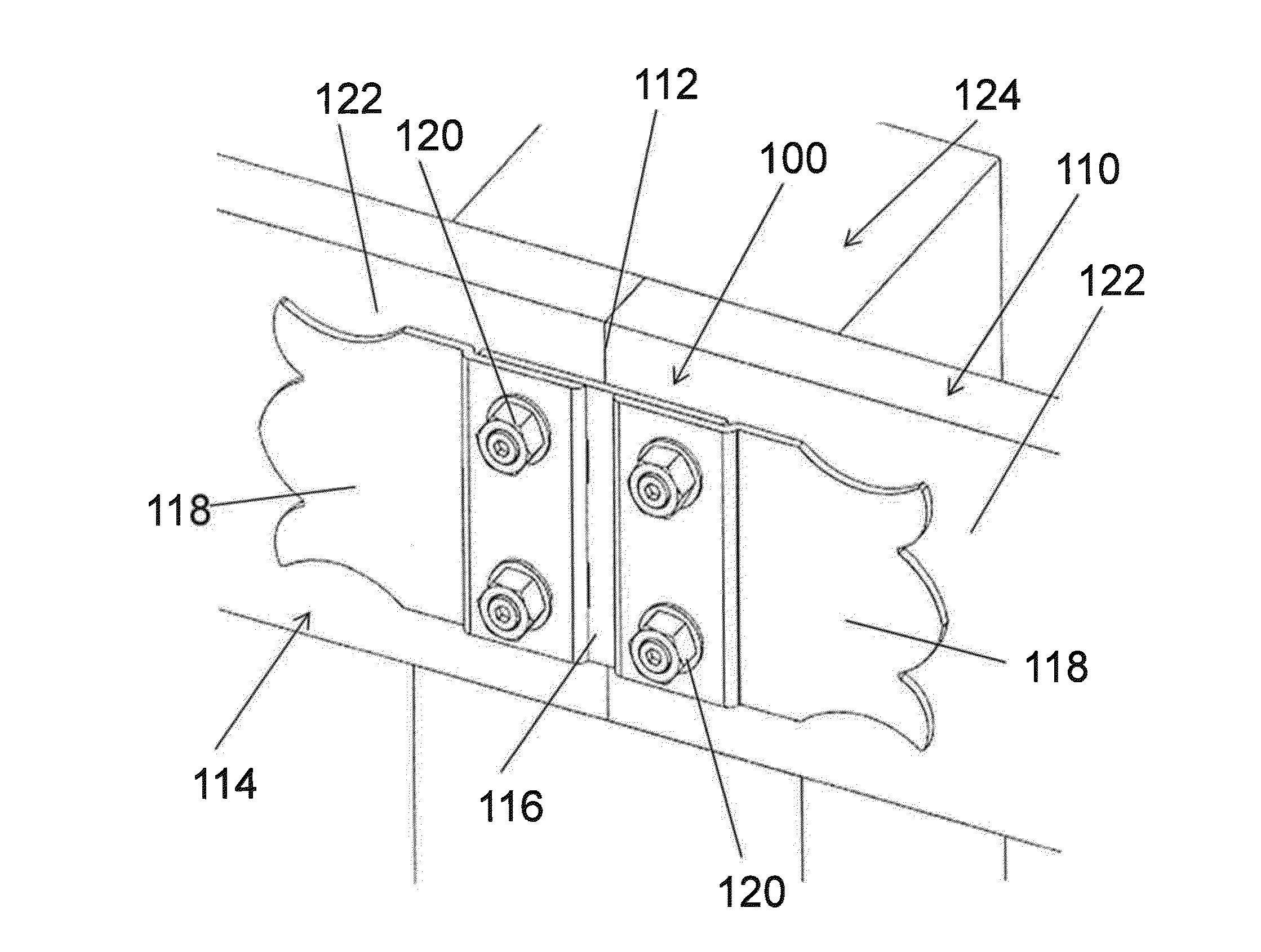
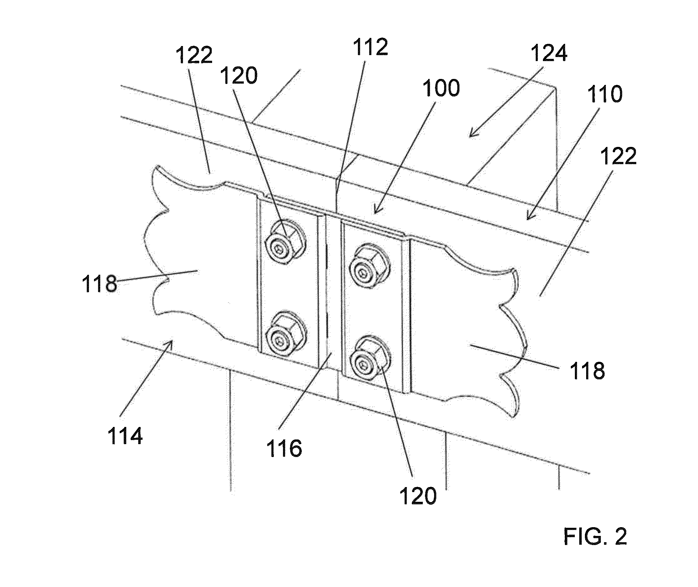
[0039]Reference is now made to FIG. 2 which shows a perspective view of a multi-piece truss plate assembly 100 used for attaching a first structural member 110 to a second structural member 114. The first structural member 110 abuts the second structural member 114 at a joint 112. The assembly 100 includes a bridge plate 116 and a plurality of stirrup plates 118. The bridge plate 116 extends across the joint 112. Each stirrup plate 118 interlocks with the bridge plate 116 in a manner to be described in detail below. A mounting device 120, such as a screw or bolt, is used to attach the stirrup plate 118 and bridge plate 116 to the side surface 122 of the structural member 110 or 114.

[0040]The mounting device 120 may further be used to attach the structural member 110 or 114 to another structural member 124 (if present) on the opposite side of the surfaces 122. A construction of this type is shown in FIG. 2.

[0041]If the another structural member 124...


PUM


Abstract

A first structural member and a second structural member meet at a joint of a truss triangular unit. A bridge plate includes a central portion that spans across the joint. The bridge plate includes a first peripheral portion extending from the central portion in a direction of the first structural member and a second peripheral portion extending from the central portion in a direction of the second structural member. Each peripheral portion includes a slot and a first opening. A stirrup plate is provided for each peripheral portion. Each stirrup plate includes an interlocking mounting flange having an extending tab member received by the slot and a second opening aligned with the first opening. A mounting device extends through the aligned first and second openings to secure the stirrup plate and bridge plate to the underlying structural member.

Description

PRIORITY CLAIM[0001]This application claims priority from U.S. Provisional Application for Patent No. 61 / 669,180 filed Jul. 9, 2012, the disclosure of which is incorporated by reference.BACKGROUND OF THE INVENTION[0002]1. Technical Field of the Invention[0003]The present invention relates generally to a truss plate for supporting a connection of two structural members and, in particular, to an ornamental truss plate having a multi-piece construction.[0004]2. Description of Related Art[0005]Many construction projects require the fabrication of a truss, for example a roof truss or a deck truss. A truss is a structure comprising one or more triangular units constructed from straight structural members connected together at joints commonly referred to as nodes or panel points. The most commonly recognized truss is a planar truss in which all the straight structural members and nodes (panel points) lie within a two dimensional plane. The connection between two structural members in a tru...

Claims


Application Information

Patent Timeline
IPC IPC(8): E04B1/41E04C3/02
CPCE04B1/40E04C3/02E04B1/2604E04B2001/2644E04C3/17E04B2001/2457E04B2001/2415E04B1/388
Inventor HILL, IAN A.
Owner THE HILLMAN GRP INC
Why Eureka
Try Eureka