End cap for a tubular light source

Active Publication Date: 2014-01-09
KONINKLIJKE PHILIPS ELECTRONICS NV
View PDF8 Cites 21 Cited by
  • Summary
  • Abstract
  • Description
  • Claims
  • Application Information

AI Technical Summary

Benefits of technology

[0008]According to one embodiment, the end cap may advantageously comprise a second housing portion rotationally movable in relation to the first housing portion, wherein the conductive path is formed through a rotation of the second housing portion in relation to the first housing portion when the switch element is depressed.
[0009]Additionally, the second housing portion may be at least partially arranged inside the first housing portion.
[0010]Furthermore, the end cap may comprise conductive receiving means arranged in the second housing portion and configured to receive the connector pins through a rotation of the second housing portion in relation to the first housing portion, and wherein the electrically conductive receiving means are configured to be axially aligned with the connector pins only when the switch element is depressed. Consequently, the connector pins may preferably extend into the second housing portion where the connection between the pins and the receiving means is made. The electrically conductive receiving means may advantageously be arranged on a plate which in turn is mechanically connected to the axially movable switch element. The axial alignment of the electrically conductive receiving means and the connector pins thereby enables the connection between the socket and the light source as the end cap is mounted. Thus, if the rotational movement is performed without the switch element being depressed, there would be no electrical contact between the connector pins and the light source as the electrically conductive receiving means would be positioned in another axial plane. Additionally, spring means may advantageously be connected to the plate or the switch element in order to return the switch element to an un-pressed position when no external pressure is applied. The spring means may be a coil spring connected to the plate, but it may equally well be any other elastic element arranged to return the switch element to an un-pressed position.
[0011]In one embodiment, the switch element at lea

Problems solved by technology

In particular, having a push-in mechanism arranged on the end cap may cause the installer to unintentionally pus

Method used


Image

  • End cap for a tubular light source
  • End cap for a tubular light source
  • End cap for a tubular light source

Examples


Embodiment Construction

[0024]The present invention will now be described more fully hereinafter with reference to the accompanying drawings, in which currently preferred embodiments of the invention are shown. This invention may, however, be embodied in many different forms and should not be construed as limited to the embodiments set forth herein; rather, these embodiments are provided for thoroughness and completeness, and fully convey the scope of the invention to the skilled person. Like reference characters refer to like elements throughout.

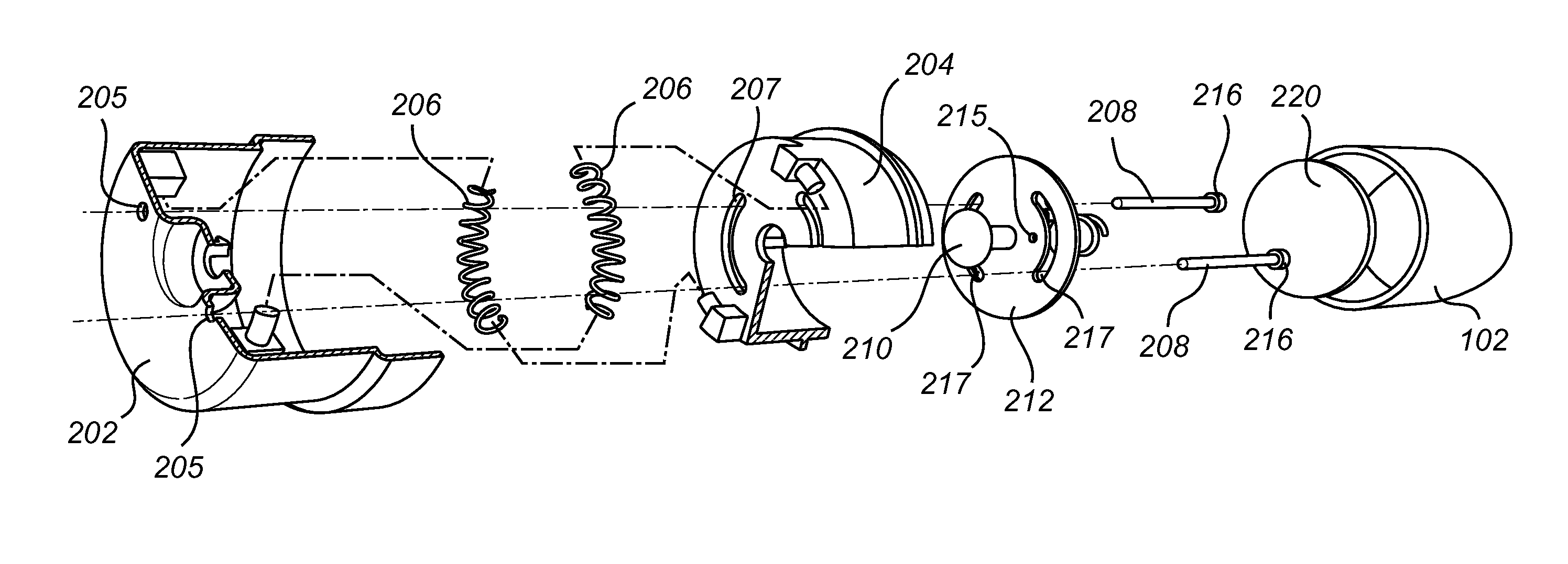
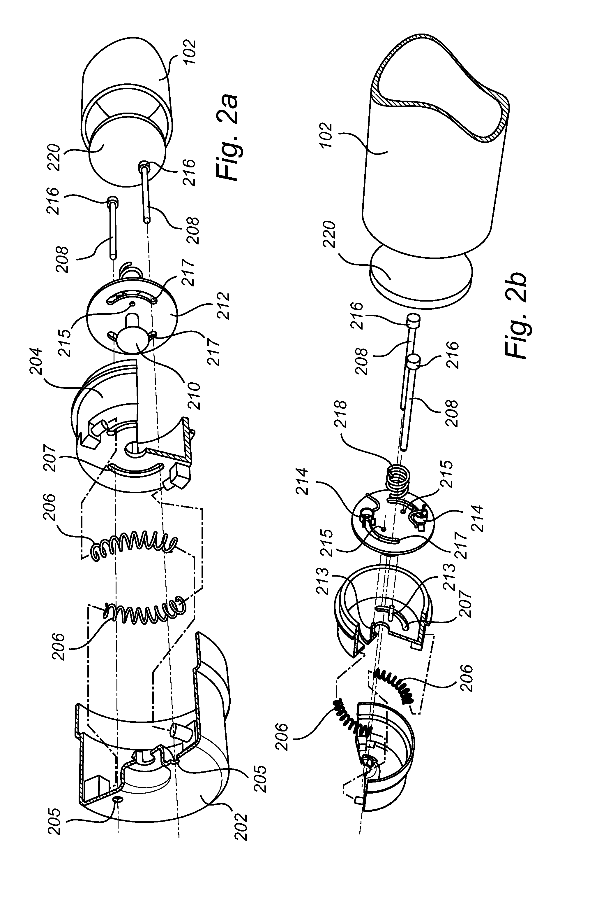
[0025]In the following, various embodiments of an end cap according to the present invention are mainly discussed with reference to an end cap for a tubular light source providing safety through a two-step mechanism including both an axial and a rotational motion. It should be noted that this by no means limits the scope of the present invention which is equally applicable to safety mechanisms for end caps where safety is provided by means of a first housing porti...


PUM


Abstract

An end cap (104) for a tubular light source (102), the tubular light source (102) configured to be arranged in a lighting fixture (106) comprising at least one socket (108), wherein the end cap (104) comprises, a first housing portion (202), two connector pins (208) at least partly arranged on an outside of the first housing portion (202) and adapted to fit in the socket (108), and a switch assembly comprising a switch element, wherein the switch assembly being adapted to form a conductive path between the socket (108) and the tubular light source (102) through a depression of the switch element in combination with a relative rotational motion of the first housing portion (202) in relation to the tubular light source (102) as the tubular light source (102) is mounted in the fixture (106).

Description

FIELD OF THE INVENTION[0001]The present invention relates to an end cap for a tubular light source, and in particular to an end cap enabling safe installation of such a tubular light source.BACKGROUND OF THE INVENTION[0002]Fluorescent lighting tubes are commonly used in a large range of lighting systems as a result of advantages such as longer life time and better luminous efficiency compared to incandescent lamps. However, in the continuous effort to reduce power consumption, it is desirable to replace conventional light tubes with still more energy efficient and environmental friendly alternatives. One such alternative is to use LED tubular light sources having a plurality of LED's arranged in a tube similar to the fluorescent tube. In order to facilitate a transition from fluorescent tube lights to LED tubular light sources, the LED tubular light sources should be configured to be mounted in already existing fixtures for fluorescent light tubes. However, the electrical circuitry ...

Claims


Application Information

Patent Timeline
IPC IPC(8): F21V25/00
CPCF21V25/00F21V19/008F21V23/04F21V25/02H01R13/71H01R33/96F21K9/272F21Y2115/10F21K9/27
Inventor VERHOEVEN, MARKGIELEN, VINCENT
Owner KONINKLIJKE PHILIPS ELECTRONICS NV
Why Eureka
Try Eureka