
Inverted machine

Active Publication Date: 2014-01-09
PARADIGM HEALTH & WELLNESS
View PDF3 Cites 3 Cited by
  • Summary
  • Abstract
  • Description
  • Claims
  • Application Information

AI Technical Summary

Benefits of technology

[0007]The main objective of the present invention is to provi

Problems solved by technology

However, because the conventional inverted machine does not have a brake mechanism mounted between the mounting frame and the connecting frame, the table of the conventional inverted machine only can be rotated at an upright angle or an inverted angel and cannot be adjusted at different angles according to the needs of the users.
In addition, when the user goes do

Method used


Image

  • Inverted machine
  • Inverted machine
  • Inverted machine

Examples


Example

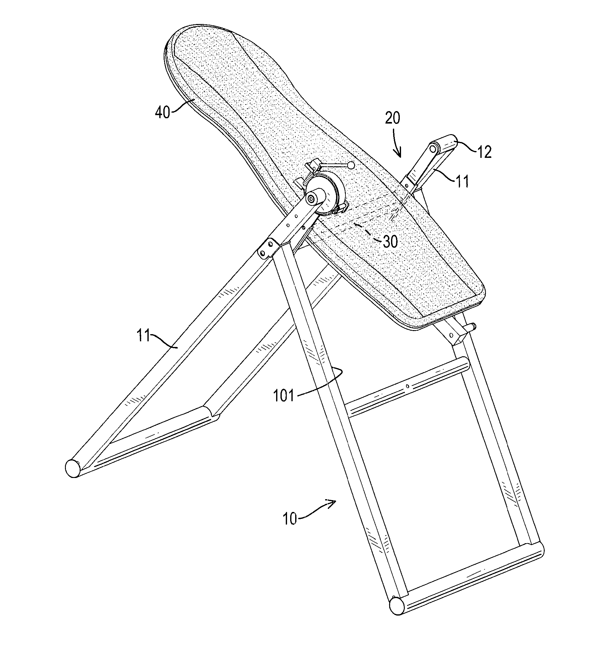
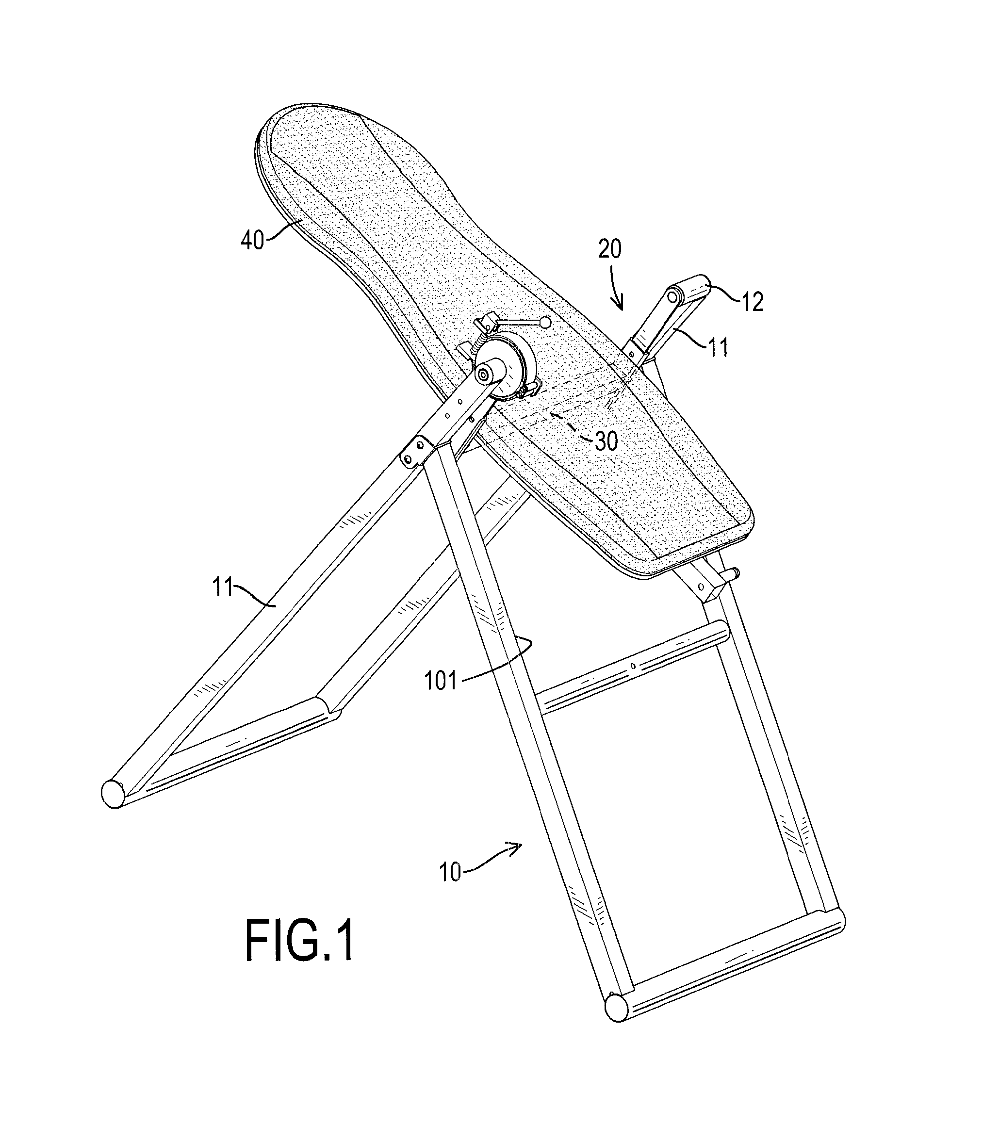
[0015]With reference to FIGS. 1 to 4, an inverted machine in accordance with the present invention has a supporting bracket 10, an orientating assembly 20, a connecting frame 30 and a table 40.

[0016]The supporting bracket 10 has a rear frame, a front frame, a swing space 101, two mounting jackets 12 and a locating sheath 14. The rear frame may be U-shaped and has two supporting shafts 11. Each supporting shaft 11 has a top end and an inner surface. The front frame may be H-shaped and is connected to the supporting shafts 11 of the rear frame below the top ends of the supporting shafts 11. The swing space 101 is defined between the frames of the supporting bracket 10.

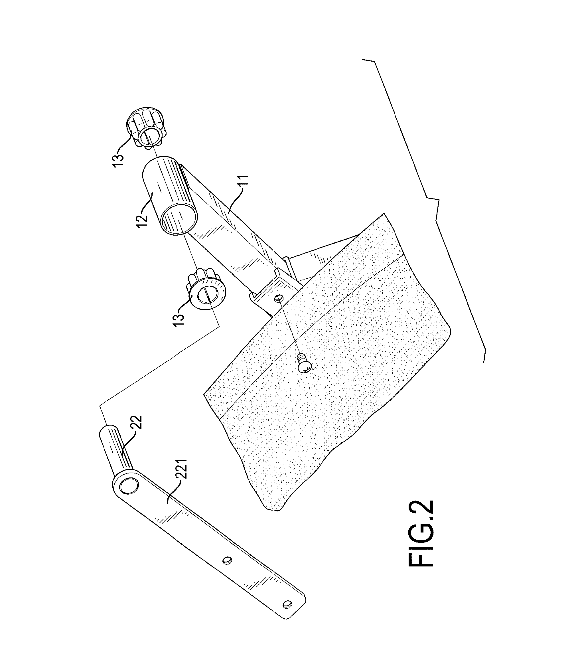
[0017]The mounting jackets 12 are cylindrical, are respectively and transversally mounted on the top ends of the supporting shafts 11 of the rear frame and align with each other. Each mounting jacket 12 has an inner end, an outer end and two liner collars 13. The inner ends of the mounting jackets 12 respectively extend ...


PUM


Abstract

An inverted machine has a supporting bracket, an orientating assembly, a connecting frame and a table. The supporting bracket has two supporting shafts, two mounting jackets and a locating sheath mounted around one of the mounting jackets. The orientating assembly is connected to the supporting bracket and has a brake locator, a rotating shaft, two clamping slices, a pulling rod, a spring and a cam device. The brake locator is connected to the mounting jacket that is connected to the locating sheath. The rotating shaft is connected to the other mounting jacket. The clamping slices are pivotally connected to the brake locator. The pulling rod is connected to the clamping slices. The spring is mounted around the pulling rod between the clamping slices. The cam device is connected to the pulling rod. The connecting frame is connected to the orientating assembly. The table is mounted on the connecting frame.

Description

BACKGROUND OF THE INVENTION[0001]1. Field of the Invention[0002]The present invention relates to an inverted machine, and more particularly to an inverted machine that can be operated easily and safely.[0003]2. Description of Related Art[0004]A conventional inverted machine has a mounting bracket, a connecting frame and an ankle clamp assembly. The connecting frame is pivotally connected to the mounting frame and has a top face, a lower end and a table. The table is mounted on the top face of the connecting frame. The ankle clamp assembly is connected to the lower end of connecting frame and clamps and holds a person's ankles when the table is pivoted to an inverted position. When the connecting frame is rotated relative to the mounting frame to allow a person to be upside down, feet-up posture, and this can stretch the back muscles and can achieve fitness results of spine, knee, ankle and other joints of the person.[0005]However, because the conventional inverted machine does not h...

Claims


Application Information

Patent Timeline
IPC IPC(8): A63B26/00
CPCA61H1/0292A61H1/02F16D49/16F16D2127/04A63B26/00A61H1/0229F16D2121/14
Inventor WEI, TSAO-KUANG
Owner PARADIGM HEALTH & WELLNESS
Learn More