
Methods and devices for installing standard and reverse shoulder implants

a technology for shoulder implants and implants, applied in the field of joint implants, can solve problems such as limited function, subsequent dislocations, loosening and wear of prosthetic components,

Active Publication Date: 2014-01-09
SMITH & NEPHEW INC
View PDF9 Cites 121 Cited by
  • Summary
  • Abstract
  • Description
  • Claims
  • Application Information

AI Technical Summary

Benefits of technology

The patent text describes a method for replacing a humeral head with a pre-determined template and implant. The method involves obtaining a 3D scan of the humeral head and using it to determine the anatomy of the patient's humeral head. This anatomy is then used to create a cutting block for resecting the humeral head. The method also includes determining the desired inclination and retroversion of the humeral head. The use of pre-determined templates and implants allows for a more precise and accurate replacement of the humeral head. The technical effect of this method is to improve the accuracy and efficiency of humeral head replacement surgery.

Problems solved by technology

Incorrect inclination and version can lead to problems including limited function, subsequent dislocations, and prosthetic component loosening and wear.
Unfortunately, with existing implants and installation techniques, these critical parameters are chosen in a freehand manner.
In more severe cases, such as irreparable rotator cuff rupture, standard shoulder implants, as described above, would not provide sufficient pain-free joint stability or an adequate range of motion.
The above procedures, while providing significant advancements, still suffer from certain drawbacks.
Unfortunately, the placement of the guidewire is performed using a freehand technique and an alignment tool.

Method used


Image

  • Methods and devices for installing standard and reverse shoulder implants
  • Methods and devices for installing standard and reverse shoulder implants
  • Methods and devices for installing standard and reverse shoulder implants

Examples


Embodiment Construction

[0216]The following description of the depicted embodiment(s) is merely exemplary in nature and is in no way intended to limit the invention, its application, or uses.

[0217]Humeral Head Resurfacing and Humeral Head Templates

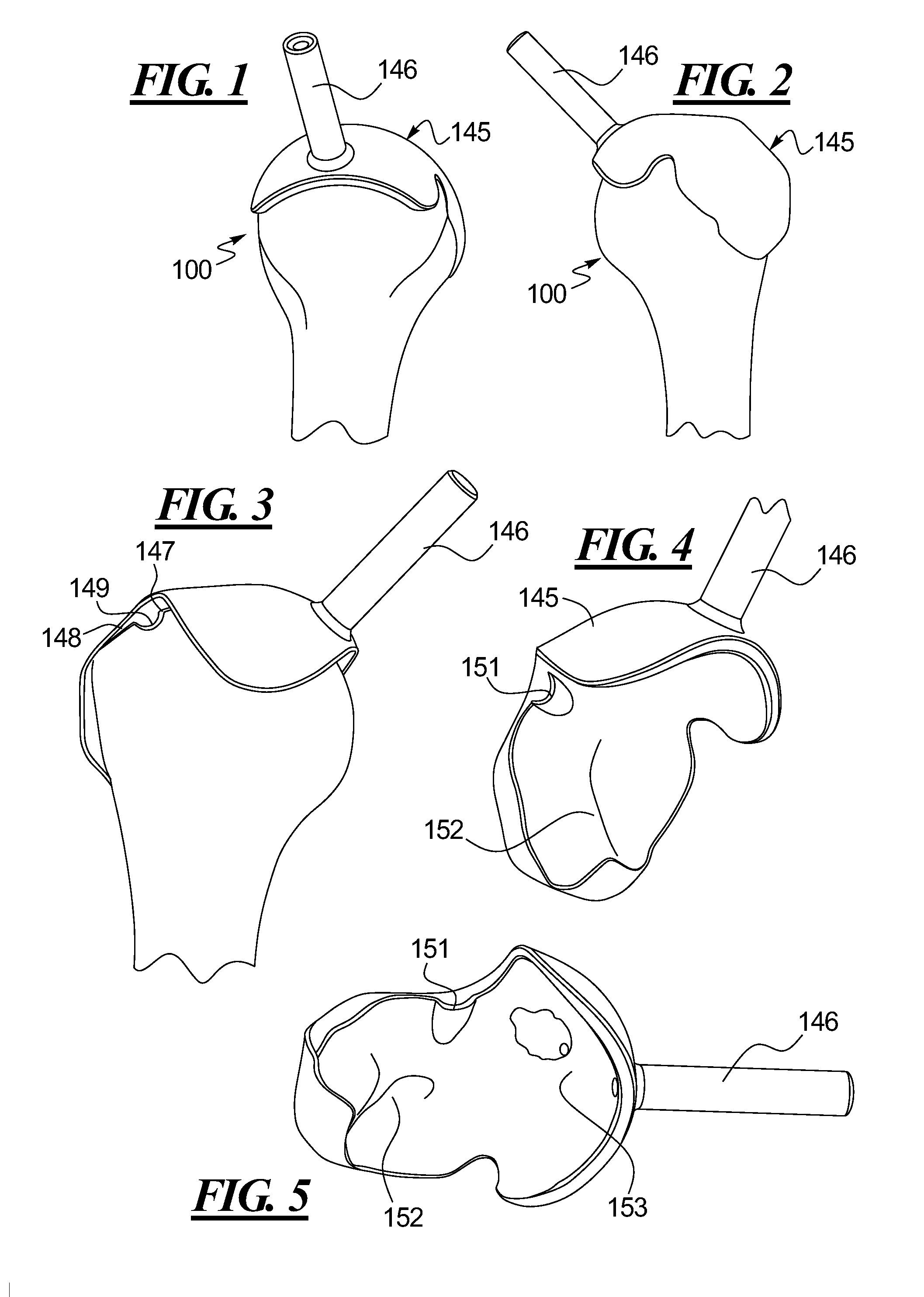
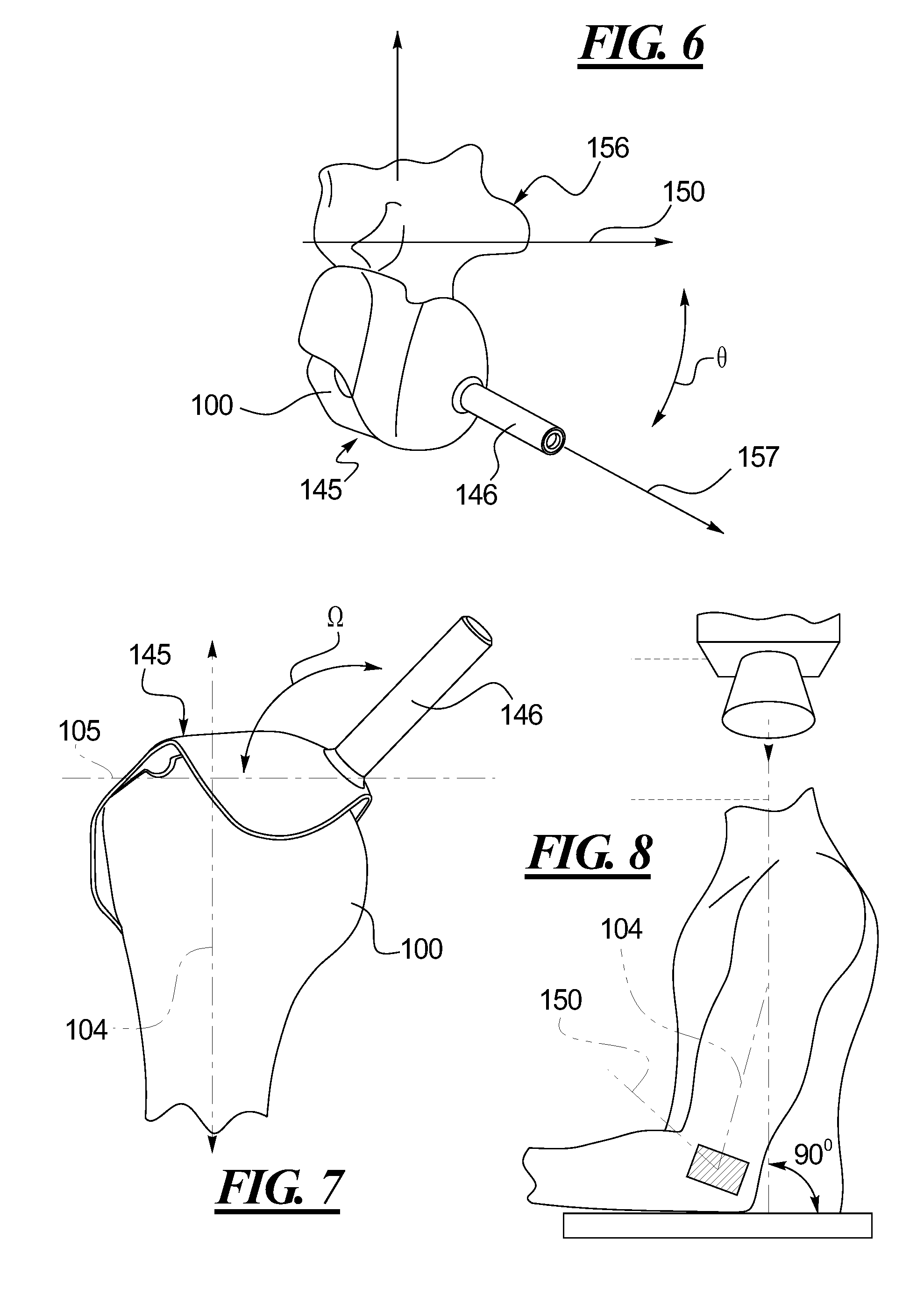
[0218]Disclosed methods and devices for resurfacing humeral heads are shown and described in FIGS. 1-12. Turning to FIGS. 1-2, the humeral head 100 is imaged using a computerized axial tomography (CAT or CT) scan or a magnetic resonance image (MRI) or other suitable 3D scanning method. The 3D scan is used to provide patient specific anatomy that can be used to generate a custom humeral head template 145 that may be equipped with a guide 146 for receiving a guide wire. The guide 146 and humeral head template 145 may be fabricated separately or as a unitary structure. The amount of patient-specific anatomy that can be used to stabilize the humeral head template 145 may be determined by the surgeon or may be standardized based upon future established procedures or b...


PUM

PropertyMeasurementUnit
Angleaaaaaaaaaa

Abstract

Surgical procedures, tools and implants are disclosed for both conventional and reverse shoulder implant surgeries. The improved procedures, tools and implants relate to humeral head resurfacing, humeral head resection for standard implants, humeral head resection for reverse shoulder implants, glenoid resurfacing for standard shoulder implants and glenoid resurfacing for reverse shoulder implants. 3D scans and x-rays are used to develop virtual models of the patient anatomy, identify patient specific landmarks for anchoring guide wire installation blocks, templates and drill guides. 3D scans are also used to design patient specific tools and implants for the shoulder implant procedures and to pre-operatively determine the appropriate inclination and retroversion angles.

Description

CROSS REFERENCE TO RELATED APPLICATION[0001]This application claims priority to U.S. Provisional Patent Application Ser. No. 61 / 373,092, filed on Aug. 12, 2010, which is incorporated herein by reference.TECHNICAL FIELD[0002]This disclosure relates generally to joint implants and more particularly to systems and methods for facilitating installations of various forms of shoulder implants that are specific to the anatomy of the patient.BACKGROUND[0003]When a joint, such as a shoulder, hip or knee, becomes impaired due to arthritis, disease or trauma, it is sometimes necessary to replace all or part of the joint with one or more prostheses to restore function. Four anatomical characteristics that relate to shoulders are humeral and glenoid inclination and humeral retroversion and glenoid version, all of which can change as disease in the shoulder joint progresses.[0004]For purposes of this disclosure, humeral inclination is defined as the angle between the plane of the anatomical neck ...

Claims


Application Information

Patent Timeline
IPC IPC(8): A61B17/17
CPCA61B17/1764A61B17/15A61B2017/568A61F2/40A61F2002/4085A61F2002/4668A61B17/1778Y10T29/49
Inventor BONIN, JR., HENRY KEITHBRUMFIELD, DAVID L.ROBERSON, JR., RAYMOND H.
Owner SMITH & NEPHEW INC
Learn More