Self-optimizing power transfer

a power transfer and self-optimization technology, applied in the direction of battery overcharge protection, safety/protection circuit, transportation and packaging, etc., can solve the problem of needing to recharge batteries

Active Publication Date: 2014-01-16
SPHERO
View PDF13 Cites 68 Cited by
  • Summary
  • Abstract
  • Description
  • Claims
  • Application Information

AI Technical Summary

Problems solved by technology

Such devices typically have

Method used


Image

  • Self-optimizing power transfer
  • Self-optimizing power transfer
  • Self-optimizing power transfer

Examples


Embodiment Construction

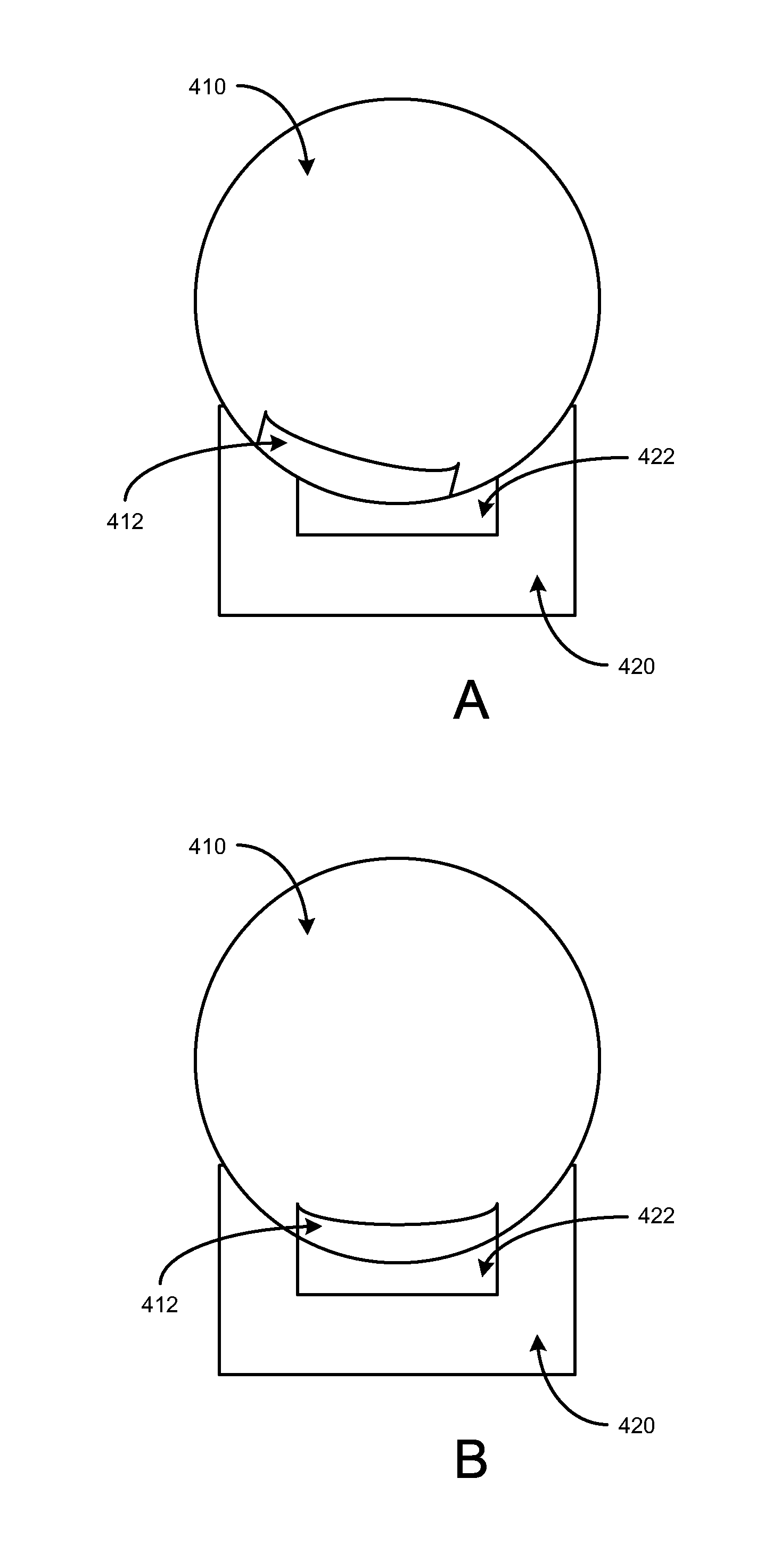
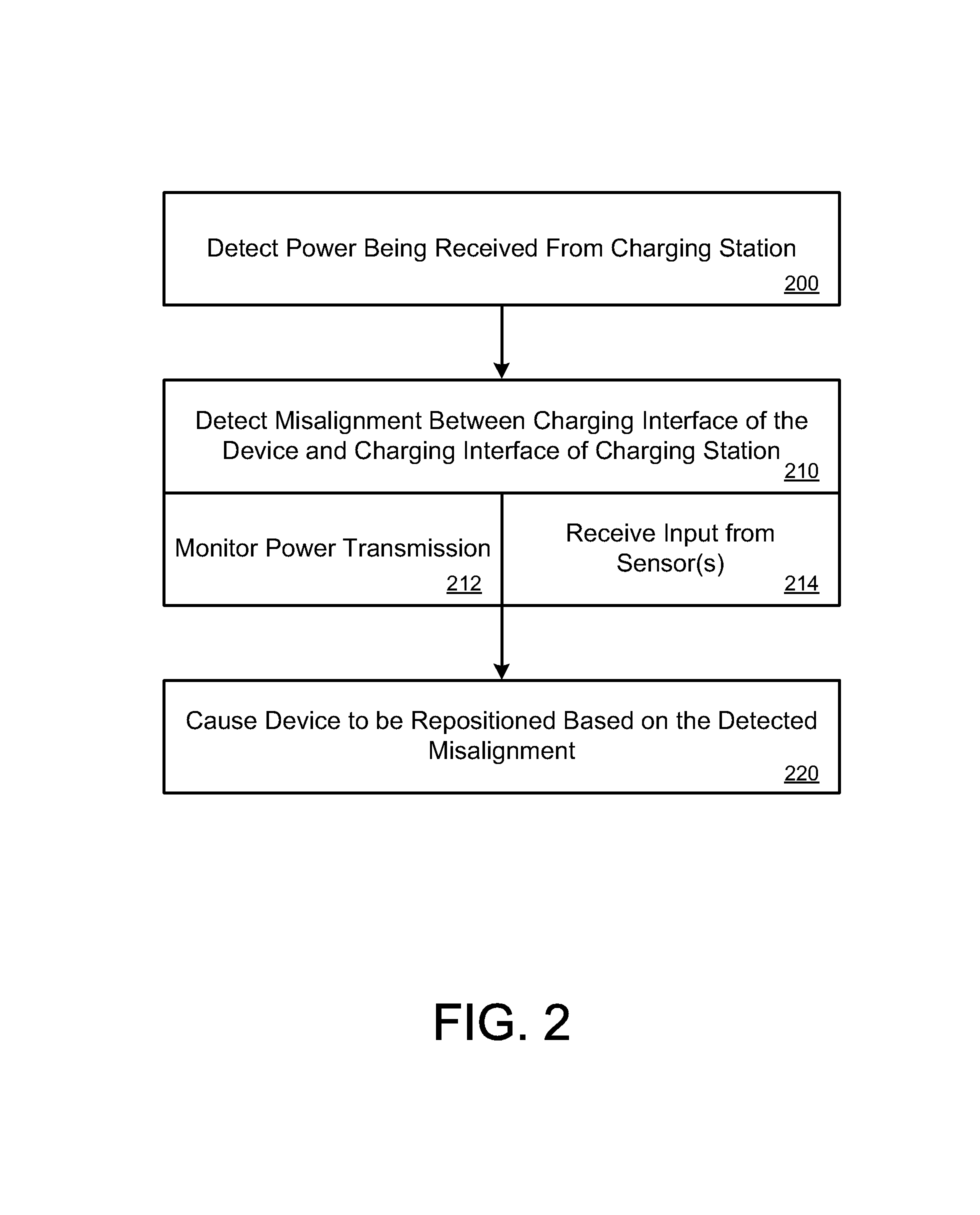
[0008]Embodiments described herein provide for a self-propelled device that is able to automatically move or adjust its position relative to a charging station or dock when it detects that its charging interface is misaligned with a charging interface of the charging station.

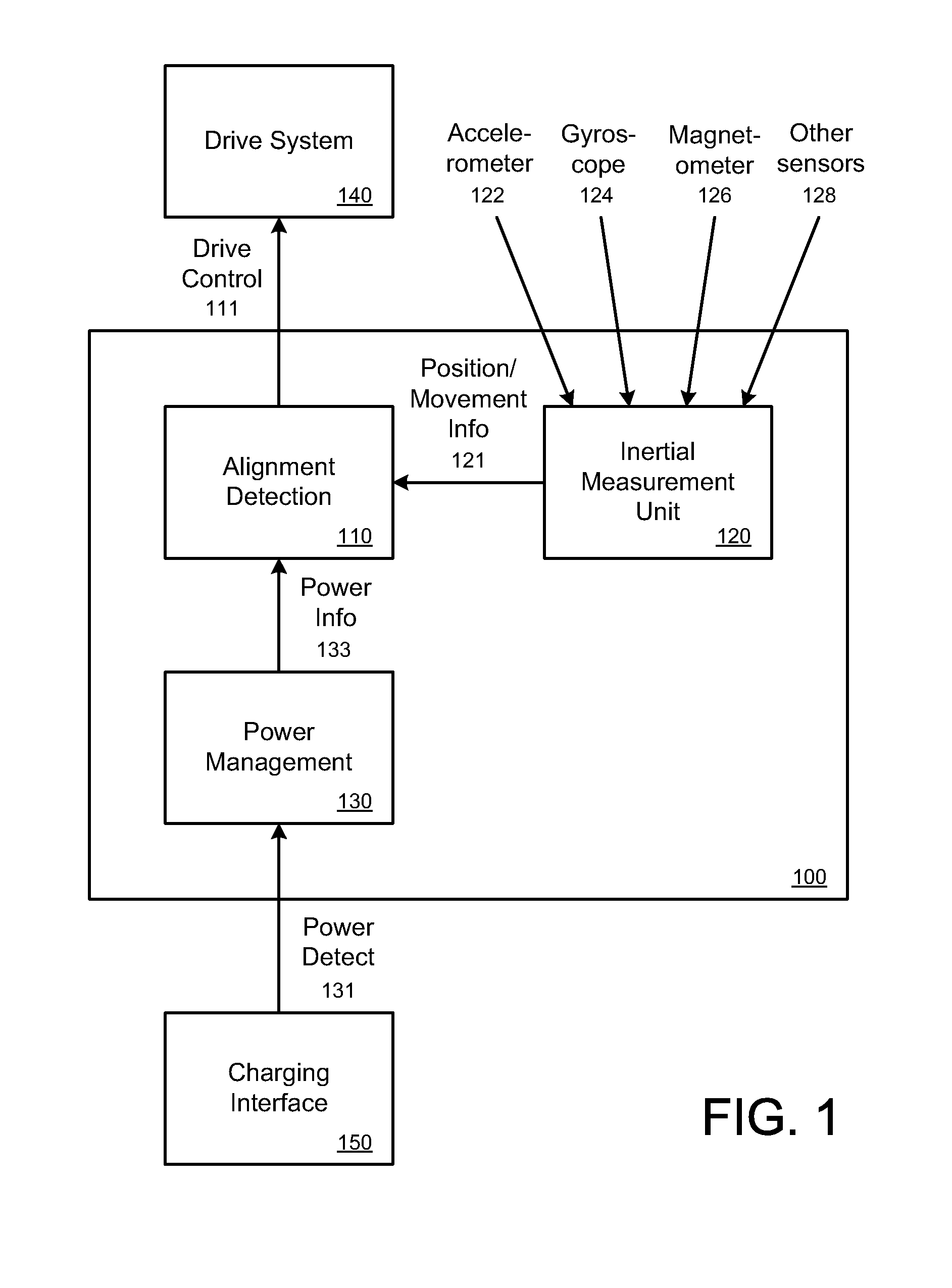
[0009]In some embodiments, the self-propelled device can include a drive system (e.g., a drive mechanism) that enables the device to move in one or more directions, and in various speeds. When the device detects that its charging interface is misaligned with the charging interface of the charging station or dock, the device can automatically control its drive system to move, thereby achieving alignment. In some cases, the self-propelled device can be referred to by different terms and phrases, including robot, robotic device, controlled device, smart device, computing device, autonomous device, remote device, and remote-controlled device. In some embodiments, a self-propelled device can be configured to autonomo...


PUM


Abstract

A method is disclosed for charging a power source of a device. The method is performed by one or more processors. The one or more processors detect that a charging interface of the device and a charging interface of a charging dock are misaligned when the device is placed into contact or operational proximity with the charging dock. The device is automatically caused to move relative to the charging dock to achieve alignment.

Description

BACKGROUND OF THE INVENTION[0001]Self-propelled devices typically operate off of internal batteries. Such devices typically have a need to recharge batteries. Many devices use charging stations or docks to recharge batteries.BRIEF DESCRIPTION OF THE DRAWINGS[0002]The disclosure herein is illustrated by way of example, and not by way of limitation, in the figures of the accompanying drawings and in which like reference numerals refer to similar elements, and in which:[0003]FIG. 1 illustrates an example system for a self-optimizing power transfer device, under an embodiment;[0004]FIG. 2 illustrates an example method for operating a self-optimizing power transfer device, according to an embodiment;[0005]FIG. 3 illustrates an example scenario of a device detecting misalignment, under an embodiment;[0006]FIGS. 4A-4B illustrate an example scenario of a self-optimizing power transfer device and a charging station, under an embodiment; and[0007]FIG. 5 illustrates an example hardware diagram...

Claims


Application Information

Patent Timeline
IPC IPC(8): H02J7/00
CPCH02J7/025H02J7/0027H02J5/005H02J50/90H02J7/0042H02J50/10H02J7/00302H02J50/80
Inventor WIRZ, BENATWELL, JAMES
Owner SPHERO
Why Eureka
Try Eureka