Eureka AIR delivers breakthrough ideas for toughest innovation challenges, trusted by R&D personnel around the world.

Method for inspecting hollow fiber filtration modules

Inactive Publication Date: 2014-01-16
DOW GLOBAL TECH LLC
View PDF2 Cites 1 Cited by
  • Summary
  • Abstract
  • Description
  • Claims
  • Application Information

AI Technical Summary

Benefits of technology

The present invention provides an effective method for inspecting hollow fiber filter modules for defects during their manufacture. This analysis can be done before the potting material is applied, and it can be automated. The method can also be integrated with the hollow fiber insertion process, so any defects can be quickly detected and remedied in real-time during manufacturing. Overall, this invention allows for better quality control and efficiency in hollow fiber filter production.

Problems solved by technology

One concern in manufacturing hollow fiber filtration modules is misplacement of hollow fiber membranes with respect to holes through a header wall.
Insertion of a hollow fiber too shallow in a hole can result in displacement of the fiber prior to potting and result in an empty hole.
Discovering defects such as these in a hollow fiber filtration module after fabrication may require discarding of the module.
Similarly, passage of large challenge particles through a module can also reveal defects and detection of particles near the surface can reveal leak locations (see, for example U.S. Pat. No. 5,411,682).

Method used


Image

  • Method for inspecting hollow fiber filtration modules
  • Method for inspecting hollow fiber filtration modules
  • Method for inspecting hollow fiber filtration modules

Examples


Embodiment Construction

[0017]“Multiple” means two or more. “And / or” means “and, or as an alternative”. All ranges include endpoints unless otherwise indicated. “Length” refers to the largest dimension and “cross sections” are perpendicular to the length.

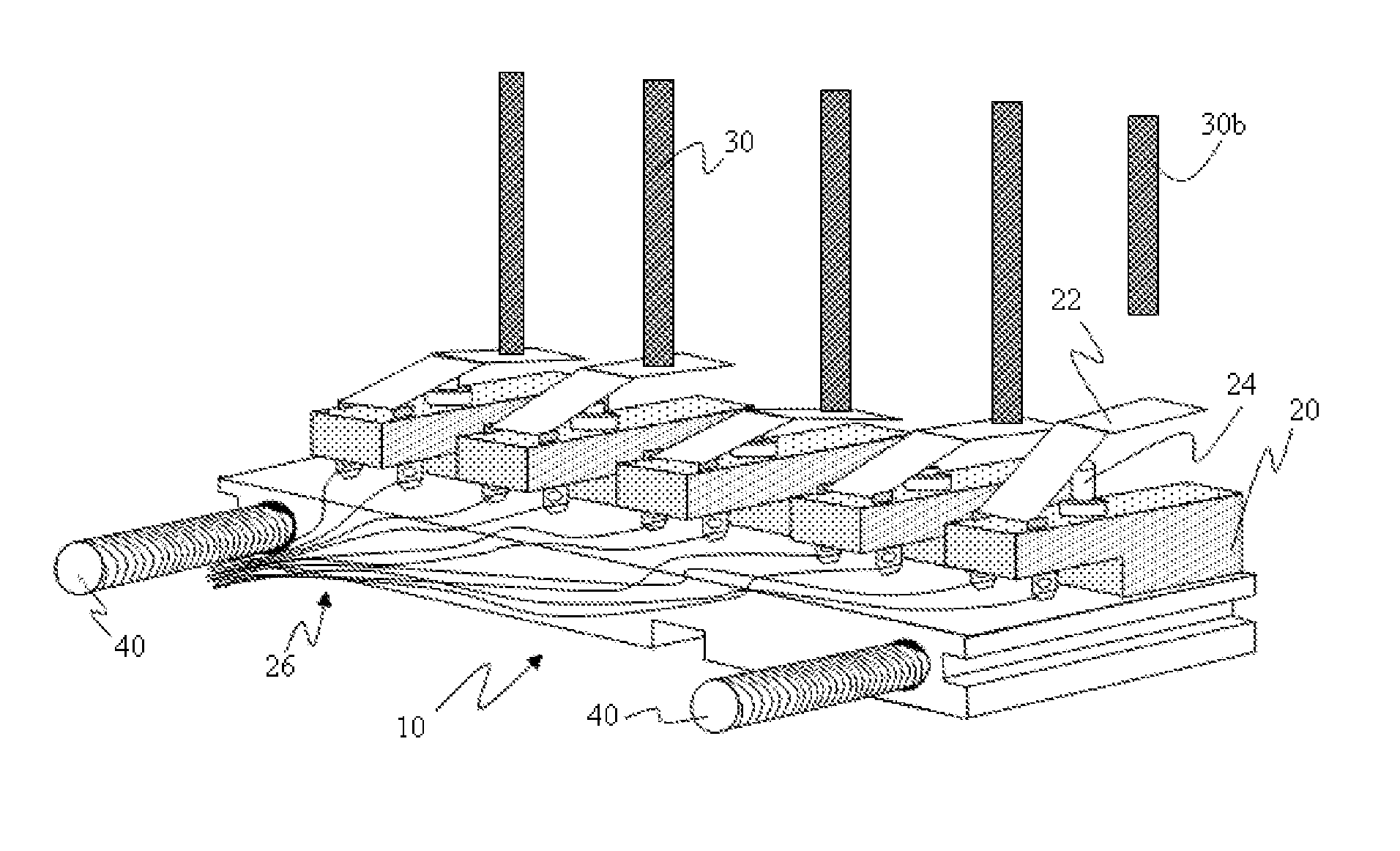
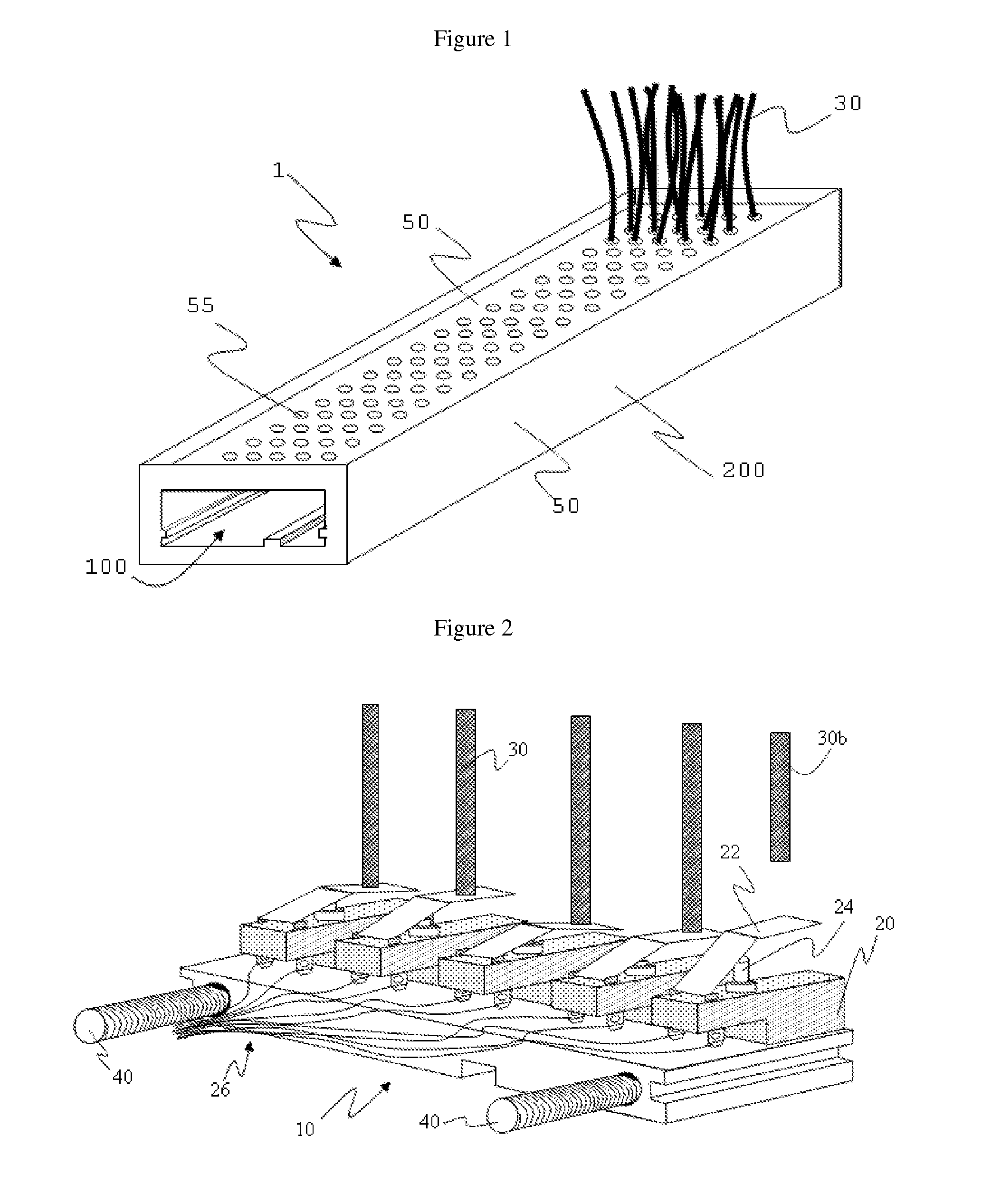
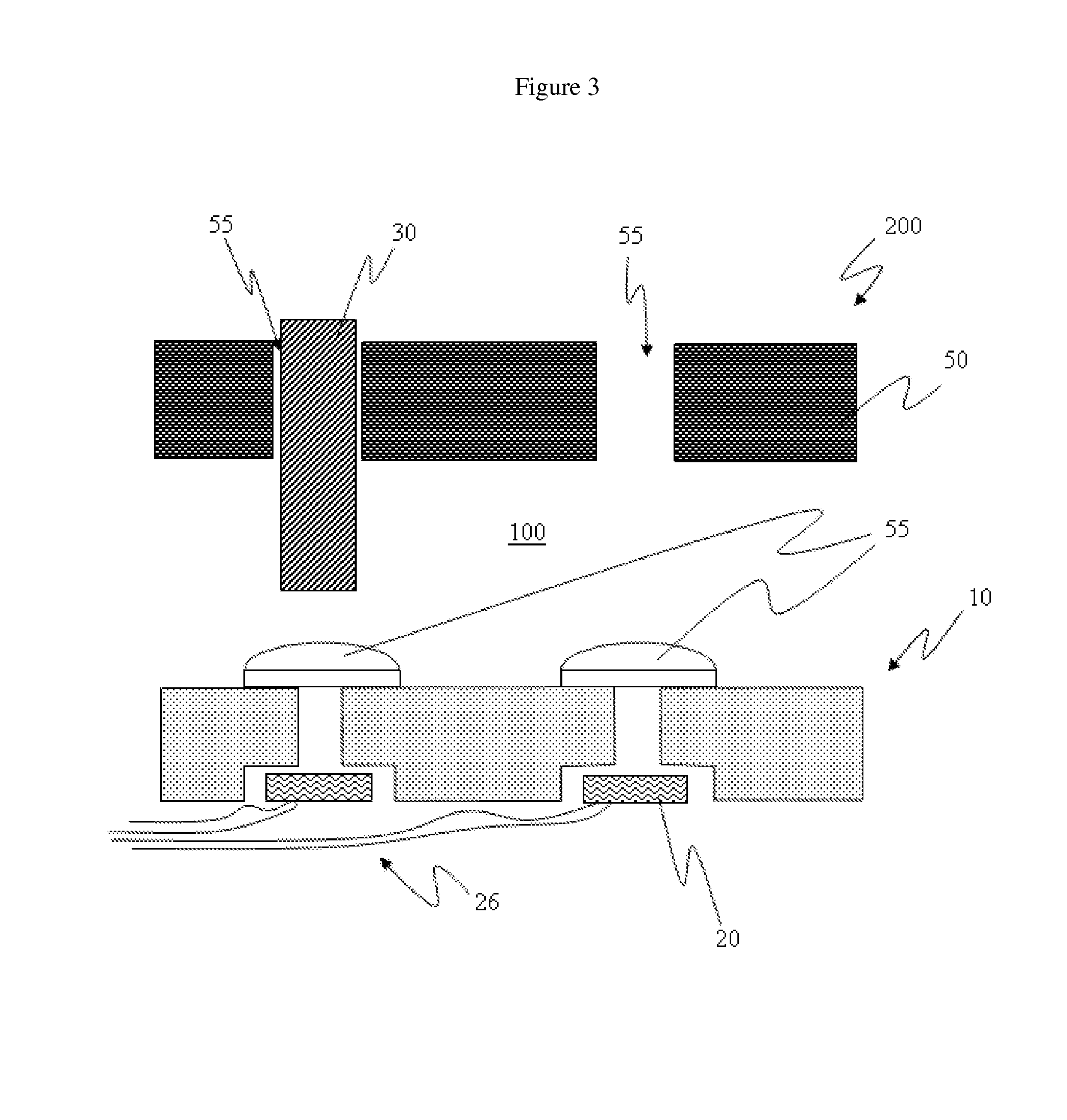
[0018]The method of the present invention is for analyzing a hollow fiber filter module (“filter module”) that comprises a membrane header assembly. Hollow fiber filter modules that can benefit from the method of this invention include both two header and single header designs. FIG. 1 illustrates an example of single header filter module 1. Filter module 1 comprises membrane header assembly (“header”) 200. Header 200 is hollow with walls 50 defining conduit 100, which extends through header 200. At least one wall 50 has holes 55 defined there-through that provide fluid communication from outside module 1 to inside conduit 100. Hollow fiber membranes 30 reside within holes 55. Filter module 1 in FIG. 1 only has a portion of holes 55 occupied by hollow fiber...


PUM

PropertyMeasurementUnit
Electromagnetismaaaaaaaaaa

Abstract

Analyze a hollow fiber filter module for defects by providing a membrane header assembly with a header having a conduit defined there-through by a wall with multiple holes and a hollow fiber membrane inserted into a hole, directing a probe device with a sensor through the conduit, receiving sensory response information with the sensor, the sensory response information containing information sufficient to identify defect in the form of a hole lacking a hollow fiber membrane, a hole that has a hollow fiber membrane inserted to a non-desired depth, or both and then interpreting the sensory response information to detect such defects if they exist.

Description

BACKGROUND OF THE INVENTION[0001]1. Field of the Invention[0002]The present invention relates to a method for inspecting hollow fiber filtration modules for proper fiber placement.[0003]2. Description of Related Art[0004]Hollow fiber filtration modules comprise a plurality of aligned semi-permeable hollow fiber membranes penetrating through the wall of a header. The header has material serving as a wall or walls that define a conduit through which liquid or gas can travel. A plurality of hollow fiber membranes extend through one or more than one wall of the header so as to extend from outside the conduit to inside the conduit. Typically, a resinous material (“potting material”) seals the hollow fiber membranes in place in the wall of the header. The hollow fiber membranes serve to filter fluid (either liquid or gas) that either travels from inside the conduit through the fiber membranes to the outside of the conduit or vice versa. Hollow fiber filtration modules are useful, for exam...

Claims


Application Information

Patent Timeline
IPC IPC(8): G01R27/32
CPCG01R27/32B01D63/02B01D65/104B01D2313/21F28F21/062B29C45/768B29C2945/76163B29C2945/76167B29C2945/76294F28F2200/00B01D63/034
Inventor AERTS, PETER E.M.JONS, STEVEN D.
Owner DOW GLOBAL TECH LLC
Why Eureka
Eureka Blog
Learn More