
Filters and method for producing filters

a filter and hollow fiber technology, applied in the direction of membranes, filtration separation, separation processes, etc., can solve the problems of high danger of contamination of finished fiber bundles, many process steps, high apparatus and cost, etc., and achieve low cost, easy production, and easy fabrication

Inactive Publication Date: 2005-10-04
GAMBRO DIALYSATOREN
View PDF11 Cites 46 Cited by
  • Summary
  • Abstract
  • Description
  • Claims
  • Application Information

AI Technical Summary

Benefits of technology

[0029]This obviates an additional processing step for providing a sealed joint between both housing portions, so that the method as a whole becomes simple and less expensive. Polyurethane can be used as a potting compound, for example. This is particularly favorable when polycarbonate or ABS (Acrylnitril-Butadiene-Styrol copolymer) is used as the material for the housing portions.
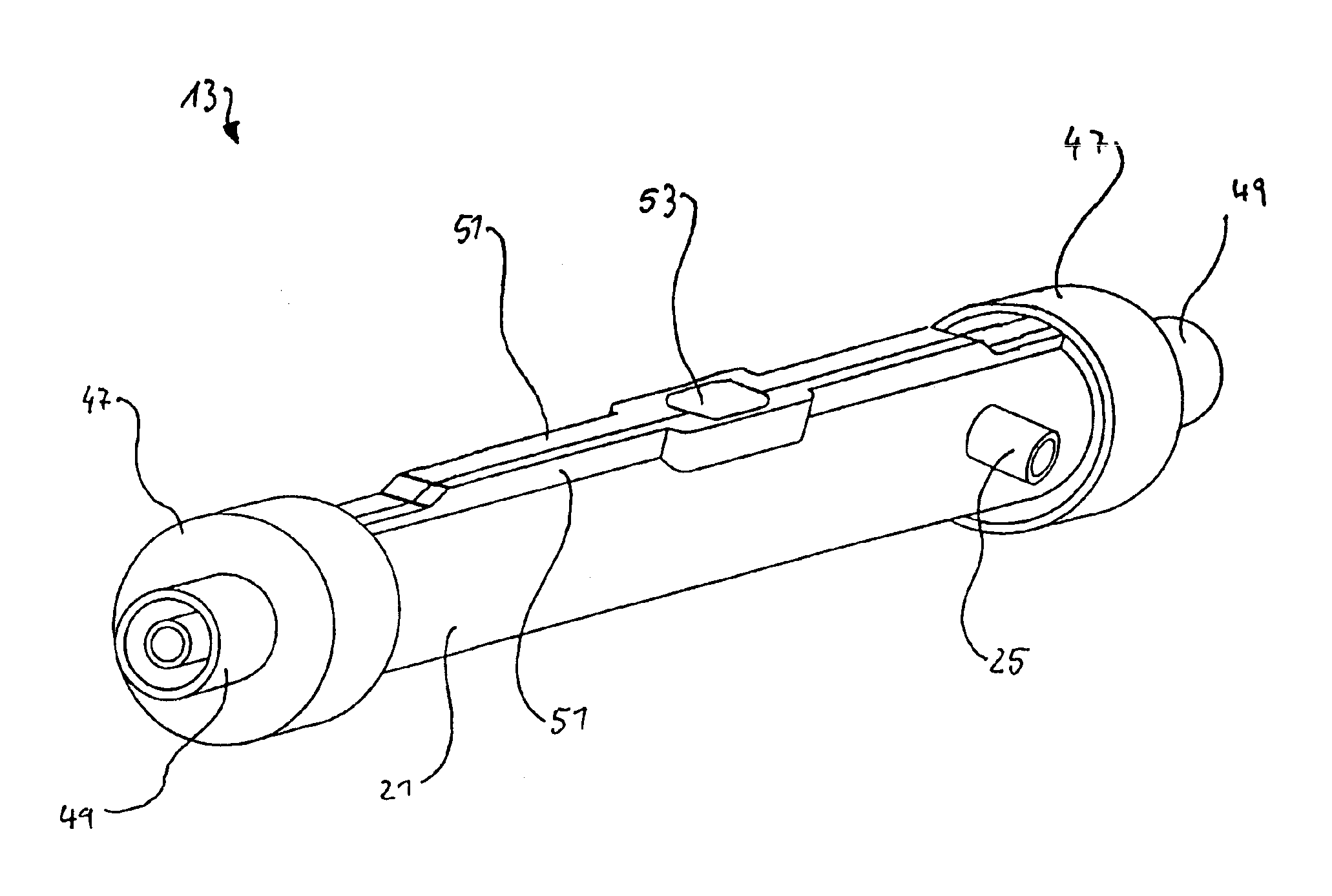
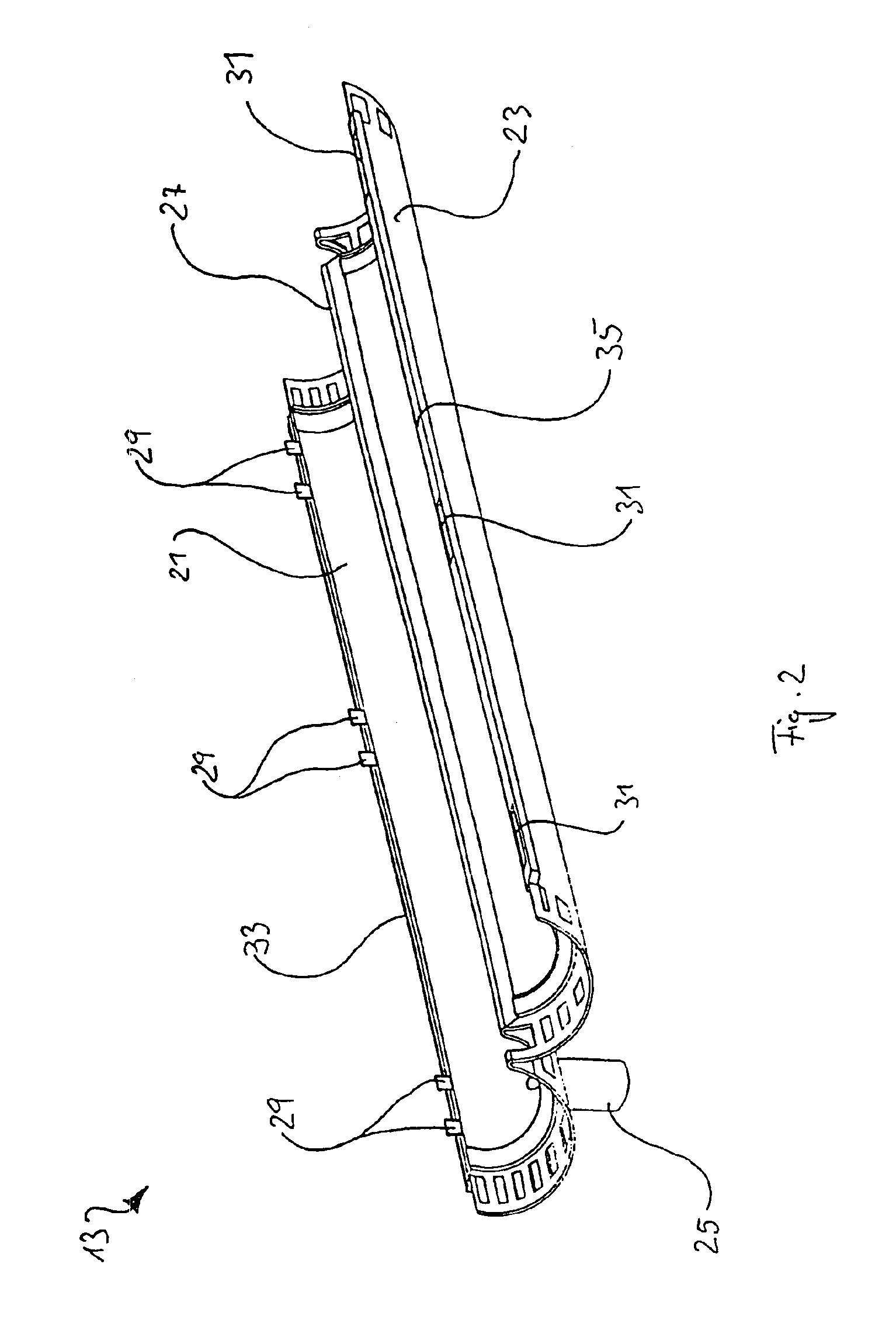
[0040]In this manner, the filters can be made simply and inexpensively without excessive outlay, as the hollow fibers can be laid one after the other in a first half-shell. Depending on the desired filter size or fiber bundle size that determines the membrane surface, the required number of hollow fibers can be laid in the filter housing. The thus formed fiber bundle can then be covered directly by the second half-shell, that is placed on the first half-shell, so that, on the one hand, damage to the hollow fibers, or the fiber bundle, by external forces is avoided, and on the other hand, the risk of contamination is reduced.

Problems solved by technology

A disadvantage of this known process is the many process steps, which are expensive in terms of apparatus and cost.
Furthermore, with this known process there is a high danger of contamination for the hollow fibers and the finished fiber bundle, as numerous processing steps are necessary and consequently much time passes before the hollow fibers or the fiber bundle is enclosed in the housing and sealed from the environment.
This known process also has the disadvantage of numerous processing steps, so that in addition to the high constructional expense and the attendant cost there also exists a high danger of contamination of the finished fiber bundle, as has been described in detail above.
Even if with this known process the risk for contamination of the finished fiber bundle is reduced, this known process still has the disadvantage of numerous processing steps.
This requires a complex device leading to high constructional expenses and attendant costs.
This known process also has the disadvantage of numerous processing steps, so that in addition to the high constructional expenses and the attendant costs there is also a high risk for contamination of the finished fiber bundle as has been described in detail above.

Method used


Image

  • Filters and method for producing filters
  • Filters and method for producing filters
  • Filters and method for producing filters

Examples


Embodiment Construction

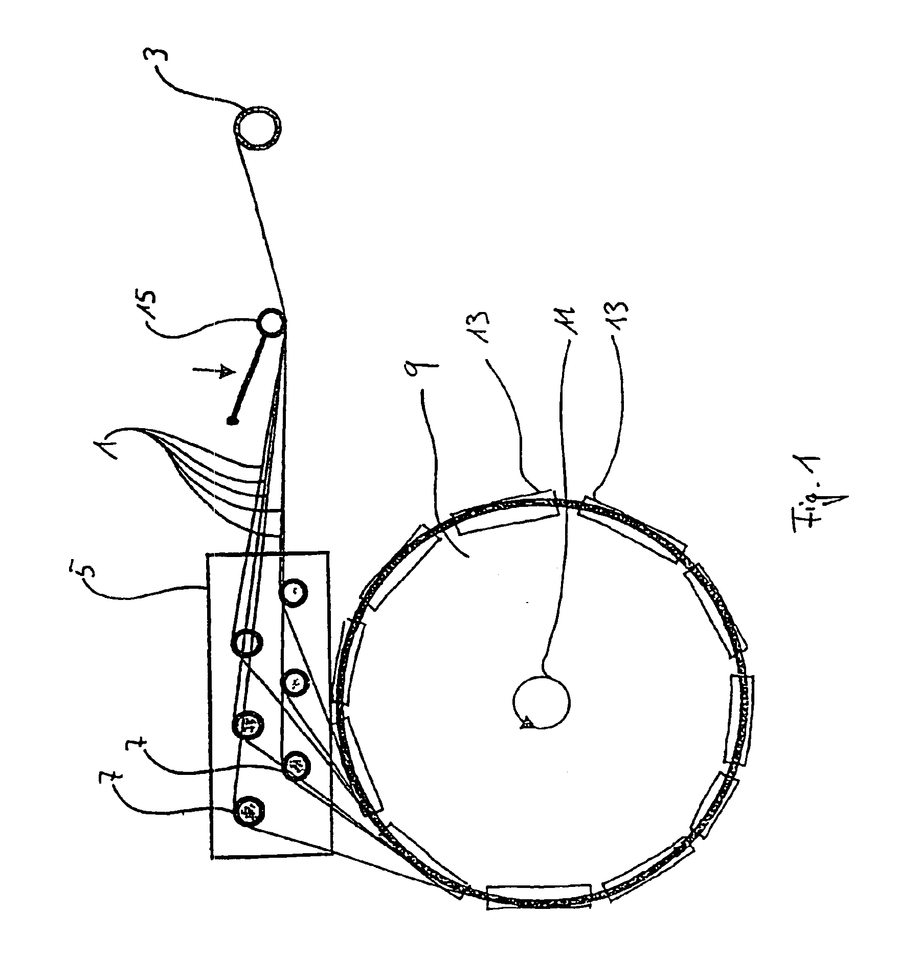
[0050]Referring to the drawings, FIG. 1 shows a side view of a winding wheel 9. On the outer circumference of the winding wheel 9 several filter housings 13 are arranged in such a way that hollow fibers 1 can be wound in the filter housing 13. The hollow fibers 1 are fed from a supply roller 3 to a distributor apparatus 5, and from there further to the winding wheel 9. It is to be noted at this point that the hollow fibers could also be supplied to the distributor apparatus directly from a production machine, or spinning machine.

[0051]Several distributor rollers 7 are arranged on the distributor apparatus 5 and each feeds individual hollow fibers 1 to the filter housings 13 arranged on the winding wheel 9. The distributor rollers 7 are movable in their longitudinal axes and are controlled such that the individual hollow fibers 1 are placed in the filter housings 13 offset relative to one another and distributed across the whole housing width. The hollow fibers 1 are unwound from the...


PUM

PropertyMeasurementUnit
Lengthaaaaaaaaaa
Flexibilityaaaaaaaaaa

Abstract

Methods and apparatus are disclosed for producing hollow fiber membrane-containing filters. The methods include laying a plurality of hollow fibers in a first portion of a filter housing to form a bundle, forming first and second portions into a filter housing, sealing the portions together, connecting the plurality of hollow fibers together at at least one end of the filter housing, connecting the hollow fibers to the filter housing, and simultaneously adhering the first and second portions of the filter housing together by applying a potting compound thereto, and cutting the ends of the hollow fibers at at least one end thereof, whereby the hollow fibers include open ends.

Description

CROSS REFERENCE TO RELATED APPLICATIONS[0001]The present application is a continuation of U.S. application Ser. No. 09 / 889,220, filed on Jul. 12, 2001 now abandoned, the disclosure of which is incorporated by reference herein.FIELD OF THE INVENTION[0002]The present invention relates to a method for producing filters with membranes of hollow fibers, for example for dialysis. More particularly, the present invention relates to a filter with membranes of hollow fibers, in which the hollow fibers are arranged as a bundle essentially parallel to one another in a tubular filter housing.BACKGROUND OF THE INVENTION[0003]Filters with membranes of hollow fibers are employed for the most diverse purposes in the field of dialysis. For example, such filters are utilized for haemodialysis, in which blood is passed through the inside of hollow fibers constructed with semi-permeable walls and dialysis fluid is caused to flow past the outside of the hollow fibers. During this process, diverse convec...

Claims


Application Information

Patent Timeline
IPC IPC(8): B01D63/02B01D65/00
CPCB01D63/021B01D65/00B01D2313/13B01D63/0233
Inventor DANNENMAIER, JURGENRAABE, HERBERTPIRNER, MANFRED
Owner GAMBRO DIALYSATOREN
Learn More