Tire printing device and method for printing onto tire surface

a printing device and tire technology, applied in the direction of printing mechanisms, transportation and packaging, other domestic objects, etc., can solve the problems of complicated operations, impairing appearance, and complicated operations

Active Publication Date: 2014-01-23
BRIDGESTONE CORP
View PDF0 Cites 8 Cited by
  • Summary
  • Abstract
  • Description
  • Claims
  • Application Information

AI Technical Summary

Benefits of technology

[0007]Therefore, in order to solve the above mentioned problems, the purpose of the present invention is to provide a tire printing device and a tire surface printing method that are capable of printing characters, patterns or the like clearly onto a tire surface without complicated operations.
[0013]According to the tire printing device and tire surface printing method of the present invention, during the printing, the printer head is swung around the axis along the circumferential direction of the tire while the printer head is moved along the width direction and the radial direction of the tire so as to maintain an appropriate distance and posture of the printer head with respect to the tire surface. Therefore, the coating material ejected from the printer head can be applied onto the tire surface without being diffused. As a result, not only the characters and patterns can be printed clearly without blurring but also cumbersome operations in the prior art, such as flattening the tire surface with the pressing roller, can be eliminated.

Problems solved by technology

The operations thus become complicated.
As a result, the characters and patterns become distorted which impairs the appearance.
In addition, since the sidewall must be pressed evenly by the roller according to the technique described in Patent Literature 2, the operations are complicated.

Method used


Image

  • Tire printing device and method for printing onto tire surface
  • Tire printing device and method for printing onto tire surface
  • Tire printing device and method for printing onto tire surface

Examples


Embodiment Construction

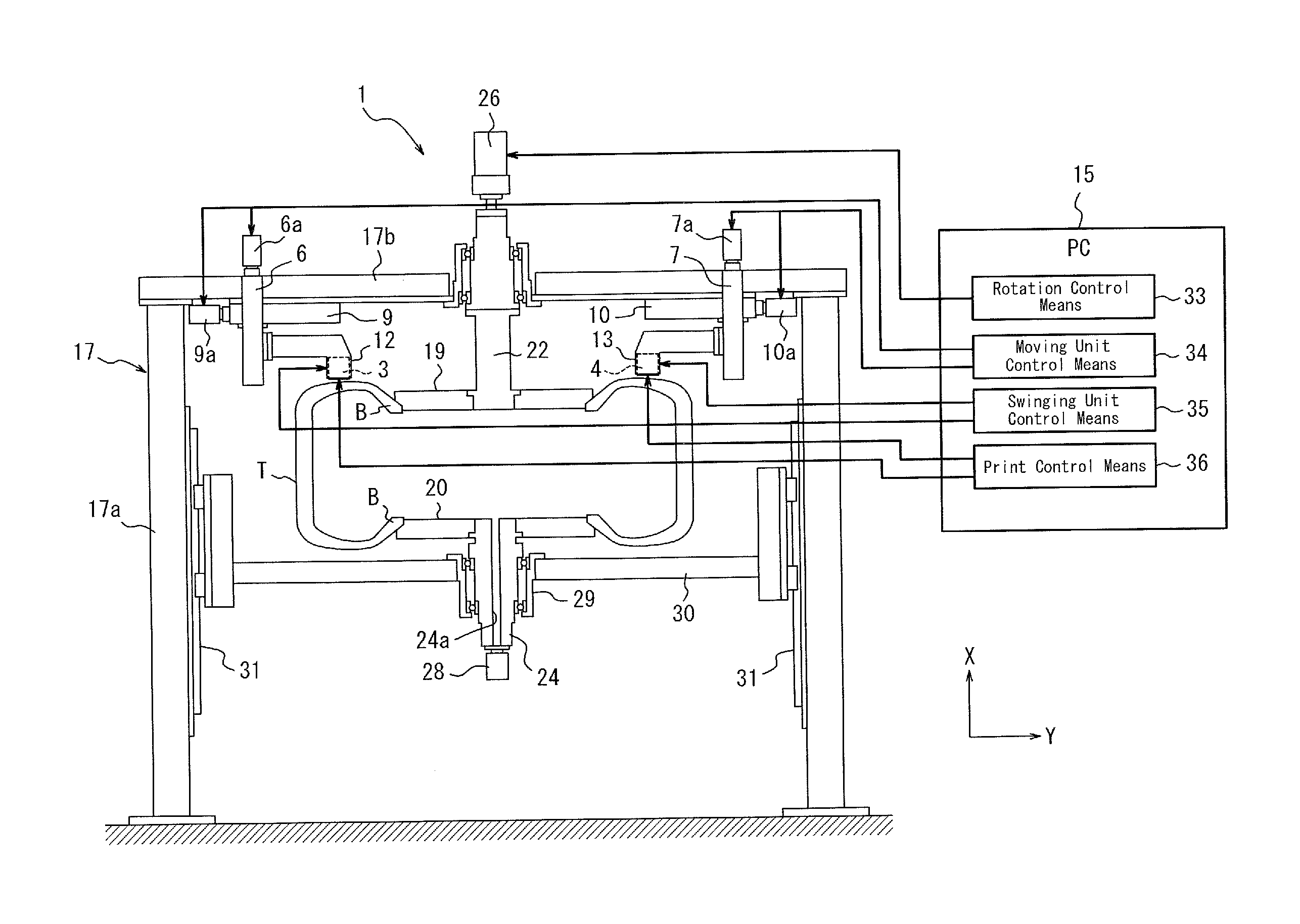
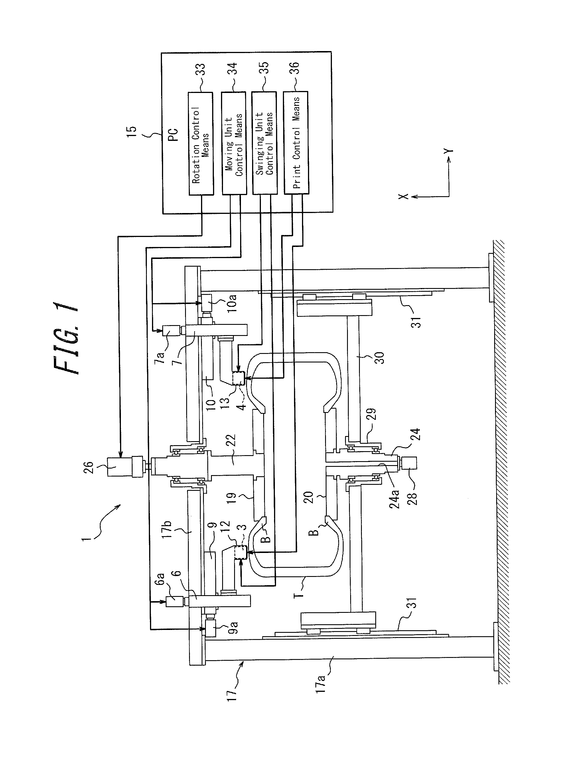
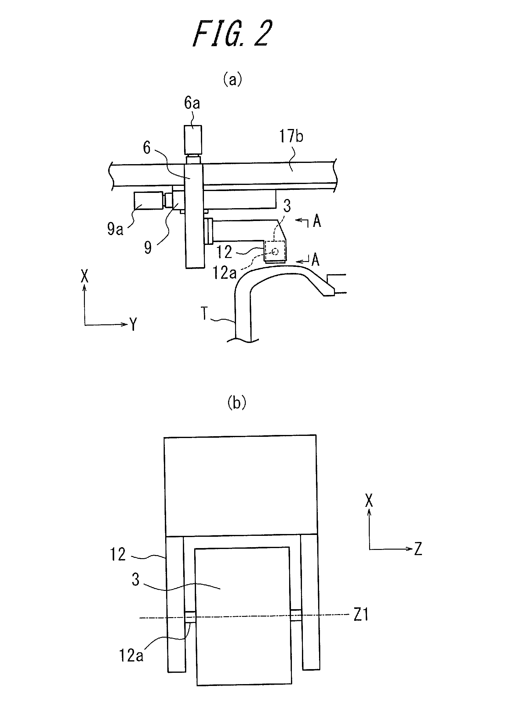
[0019]Embodiments of the present invention are described below with reference to the drawings. FIG. 1 is a schematic diagram of a tire surface printing device that performs a method for printing onto a tire surface according to one embodiment. FIG. 2 (a) illustrates a partially enlarged view of the tire surface printing device of FIG. 1. FIG. 2 (b) is a side view as viewed from the arrow A-A in FIG. 2 (a). In FIG. 2 (b), the symbol X refers to a width direction of the tire to be printed onto, the symbol Y refers to a radial direction of the tire, the symbol Z refers to a circumferential direction of the tire, and the symbol Z1 refers to an axis line along the circumferential direction Z.

[0020]The tire printing device shown in FIG. 1 includes at least one (two in the illustrated embodiment) printer heads 3, 4 that eject and apply the coating material onto a tire surface (side wall), widthwise moving units 6, 7 that move the printer heads 3, 4 along the axis direction (width direction...


PUM

PropertyMeasurementUnit
widthaaaaaaaaaa
distanceaaaaaaaaaa
internal pressureaaaaaaaaaa

Abstract

The present invention aims to provide a technique that prints characters and patterns clearly onto a tire surface without complicated operations. A tire printing device of the present invention includes a printer head that ejects and applies a coating material onto a tire surface, a widthwise moving unit that moves the printer head along the width direction of the tire, a radial moving unit that moves the printer head along the radical direction of the tire, and a swinging unit that swings the printer head around the axis along the circumferential direction of the tire.

Description

TECHNICAL FIELD[0001]The present invention relates to a tire printing device and a method for printing characters, patterns or the like on a tire surface.BACKGROUND ART[0002]As a printing device for printing characters, patterns or the like on a tire surface, a swiveling type tire printer as disclosed in Patent Literature 1 is conventionally known. The swiveling type tire printer has a function of adjusting its center position, height, and turning radius according to the size of the tire fixed to a base, and prints characters and patterns while swiveling above a tire sidewall with a strut extending along the center of the tire as a rotational axis.[0003]However, the tire sidewall is curved rather than flat, so that the position and posture of the printer head described in Patent Literature 1 with respect to the tire surface may differ depending on the position on the sidewall of the tire. In other words, as shown in FIG. 4, the distance between the sidewall of the tire T and a print...

Claims


Application Information

Patent Timeline
Patent Type & Authority Applications(United States)
IPC IPC(8): B41J23/00
CPCB60C13/001B41J3/4073B29D2030/728B41J25/308B05B13/0415B05B13/0442B41M5/0047B41M5/0064B41M5/0088B29D30/72
Inventor OGAWA, YUICHIRO
Owner BRIDGESTONE CORP
Why Eureka
Try Eureka