
Electronic apparatus and method for clipping a range out of a wide field view image

a wide field view and control method technology, applied in the field of electronic equipment, can solve the problems of user trouble, volume of data increase, etc., and achieve the effect of suitable rang

Active Publication Date: 2021-01-12
CANON KK
View PDF61 Cites 0 Cited by
  • Summary
  • Abstract
  • Description
  • Claims
  • Application Information

AI Technical Summary

Benefits of technology

[0007]The present invention is directed to a technique that enables clipping a more suitable range out of a wide field view image without complicated operations.

Problems solved by technology

An omnidirectional image has such a problem that even an originally unwanted object can be included and a problem that the volume of data increases due to inclusion of a video image in all directions.
However, it is troublesome if the user needs to determine the clipping range.

Method used


Image

  • Electronic apparatus and method for clipping a range out of a wide field view image
  • Electronic apparatus and method for clipping a range out of a wide field view image
  • Electronic apparatus and method for clipping a range out of a wide field view image

Examples


Embodiment Construction

[0019]An exemplary embodiment of the present invention will be described in detail below with reference to the accompanying drawings.

[0020]It is to be noted that the following exemplary embodiment is merely one example for implementing the present invention and can be appropriately modified or changed depending on individual constructions and various conditions of apparatuses to which the present invention is applied. Thus, the present invention is in no way limited to the following exemplary embodiment.

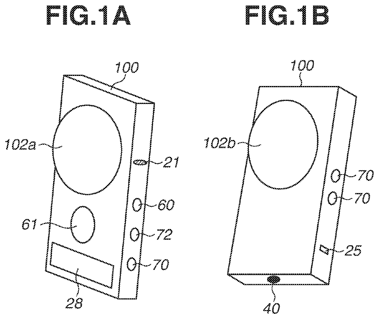
[0021]FIG. 1A illustrates a front perspective view (external view) of a digital camera 100 (imaging apparatus), which is an electronic apparatus. FIG. 1B illustrates a rear perspective view (external view) of the digital camera 100. The digital camera 100 is an omnidirectional camera (entire celestial sphere camera).

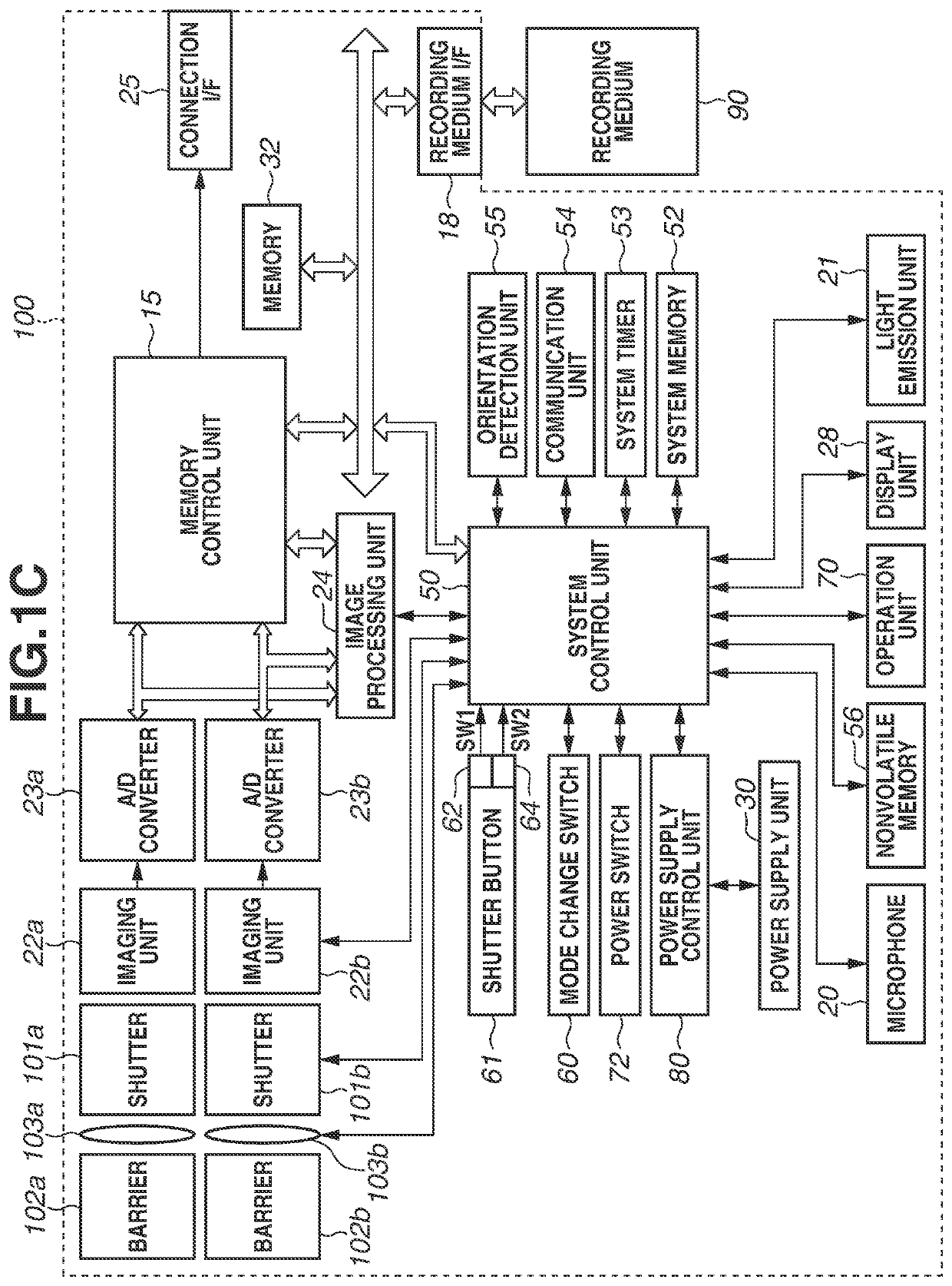
[0022]A barrier 102a is a protection window of an imaging lens 103a intended for a camera unit (i.e., barrier 102a, shutter 101a, imaging unit 22a, and A / D converter 23a)...


PUM


Abstract

An electronic apparatus includes a control unit configured to, if an operation mode in capturing a wide field view image is a first operation mode, perform control to clip out a first range in which a predetermined range with respect to a center of a clipped image includes any one of above an imaging apparatus, above in a direction of gravity, and below in the direction of gravity, and if the operation mode is a second operation mode, perform control to clip a second range in which, different from the first range, a predetermined range with respect to a center of a clipped image includes a direction perpendicular to a vertical direction of the imaging apparatus or a direction perpendicular to gravity, or to not perform clipping.

Description

BACKGROUND OF THE INVENTIONField of the Invention[0001]The present invention relates to an electronic apparatus and a method for controlling the electronic apparatus, and more particularly to a clipping control method for an image having a wide video range.Description of the Related Art[0002]There are known imaging apparatuses that can handily capture an entire celestial sphere image (omnidirectional image or all-around image) in 360° directions by one imaging operation. Imaging apparatuses that capture an image of a wide range of 180° or more, if not 360°, are also known. There are known methods for displaying a partial display range of such an image and changing and displaying the display range based on user's operations or the orientation of a display apparatus. In such a display, the display range can be mainly changed in directions of rotation about two axes, including the direction of rotation within a horizontal plane about the zenith and the direction of vertical rotation (d...

Claims


Application Information

Patent Timeline
Patent Type & Authority Patents(United States)
IPC IPC(8): H04N5/262H04N5/232
CPCH04N5/2628H04N5/23238H04N5/23245H04N23/54H04N23/50H04N23/55H04N23/667H04N23/80H04N23/63H04N23/698G06T11/60H04N23/45H04N23/62H04N23/951
Inventor KITAYA, KOKIMURAKAMI, SHIN
Owner CANON KK
Learn More