Soft tissue therapy device and method of use therefor

a soft tissue therapy and soft tissue technology, applied in the field of medical devices and processes, can solve the problems of pain, decreased stability, loss/reduction of range of motion, etc., and achieve the effects of less cluttering work space, easy gripping and manipulating, and less us

Inactive Publication Date: 2014-01-23
GRASTON TECHN
View PDF18 Cites 0 Cited by
  • Summary
  • Abstract
  • Description
  • Claims
  • Application Information

AI Technical Summary

Benefits of technology

The present invention provides a connector that can be easily attached and detached from a rigid tool member, allowing for the use of the tool in both electro stimulation and soft tissue therapy without the need for electrical stimulation. The connector is adaptable for use with a wide variety of tools, reducing clutter and confusion for users. This feature also allows for the use of a single electrical stimulation source with multiple tools, providing convenience and efficiency for users.

Problems solved by technology

The patent text discusses the problem of soft tissue dysfunction, which can occur due to inflammation or scar tissue buildup. Current methods of soft tissue therapy involve manual massage using tools, but this can be difficult to apply consistent pressure and may cause discomfort or injury. The patent aims to improve the effectiveness of soft tissue therapy by adding electrical stimulation therapy using a set of tools and techniques. The technical problem addressed is the need for a connection system to connect an electrical source to massage tools, allowing for the use of both manual and electrical therapy in a single treatment.

Method used


Image

  • Soft tissue therapy device and method of use therefor
  • Soft tissue therapy device and method of use therefor
  • Soft tissue therapy device and method of use therefor

Examples


second embodiment

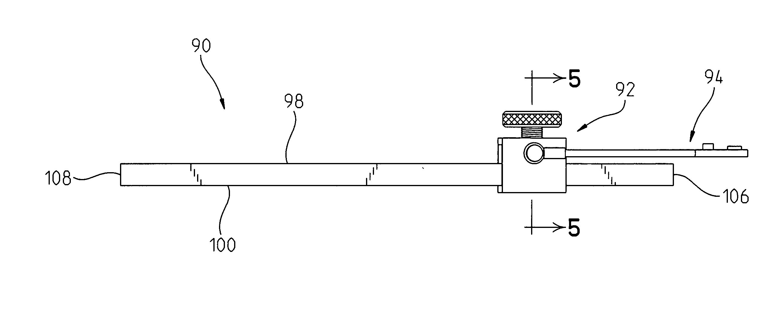
[0109]Similar to the embodiment shown in FIG. 1, the second embodiment connector 200 also includes a screw type clamping screw 212 for fixedly coupling the tool 90 in a desired position within an interior passageway 218 of the connector 200, and fixedly positioning the tool 90 in place. Additionally, the clamping screw connector 212 helps to hold the lower surface 100 of the tool 90 in a closely engaged and contacting position with an upper interior surface 282 of the lower member 206 to provide a good electrical connection between the tool 90, and the connector 200.

[0110]As best shown in FIG. 10, the connector 200 includes an interior passageway that extends between a first open side member 304 and a second open side member (not shown). The interior passageway 114 includes a relatively reduced width portion 216, and a relatively enlarged width portion 218. Enlarged width portion 218 is provided for being wide enough to accept the full width of the tool 90. Additionally, the shoulde...

embodiment 500

[0139]Turning now to FIGS. 19A-22B, an alternate embodiment magnetically attachable coupler 600 is shown for use in connection with a therapy tool. The magnetically attachable coupler 600 is, from a functional standpoint, a variant of the embodiment 500 shown in FIGS. 19-22, with the primary difference being that coupler 600 includes three magnet receiving cavities 604, 606, 609, and three magnets 605, 607, 611 for being received in the respective three cavities.

[0140]In particular, an electrical source (not shown) is provided that contains a plug (not shown), that is insertable into a plug receptacle 622 of the coupler 600 for providing a source of current to the coupler 600. The current so provided is then transferred to a therapy tool (e.g. tool 90) to which the magnetically attachable coupler 600 is attached. This current is then transferred, through a conductive path of the tool 90, to the patient's skin, and ultimately to subcutaneous tissue, such as scar tissue adhesions, upo...


PUM


Abstract

A therapy tool system includes a rigid therapy tool for passing across a patient's skin for loosening subcutaneous tissue. The rigid tool includes an electrically conductive portion engageable with a patient's skin. A current source is provided for providing an electric current. A connector member is provided that is selectively attachable and removable from the rigidtool. The tool member is coupled to the current source for conducting current between the current source and the tool. The rigid tool includes a conductive path for conducting current from the connector to the electrically conductive portion of the tool, to enable current delivered to the connector portion from the current source to be conducted to the electrically conductive portion of the tool and transferred from the tool through the patient's skin to subcutaneous patient tissues.

Description


Claims


Application Information

Patent Timeline
Owner GRASTON TECHN
Why Eureka
Try Eureka