Pressure sensitive inductive detector for use in user interfaces

a technology of inductive detector and user interface, which is applied in the direction of electronic switching, pulse technique, instruments, etc., can solve the problem of difficult use of the panel as a touch-sensitive keypad, and achieve the effect of preventing short circuits and preventing deformation

Inactive Publication Date: 2009-06-25
MICROCHIP TECH INC
View PDF6 Cites 30 Cited by
  • Summary
  • Abstract
  • Description
  • Claims
  • Application Information

AI Technical Summary

Benefits of technology

[0017]A spacer layer may be provided between the first and second inductive components. For example, the space layer may be formed of a material having a lower Young's modulus than the resilient layer. In this case, the spacer layer can act to provide additional resilience to the outer surface of the detector. The spacer layer may act to insulate electrically the first inductive component from the second inductive component to prevent short circuits.
[0018]In one arrangement, the spacer layer has apertures formed therethrough which define a sensitive region of the detector. Thus, in the region of the apertures, the resilient layer is unsupported by the space layer and can deform elastically. Outside of the apertures, the spacer layer supports the resilient layer and prevents deformation. Thus, the spacer layer acts to isolate mechanically the sensitive region(s) of the detector. In a convenient construction, the spacer layer may be formed of a rigid material, such as printed circuit board substrate material.

Problems solved by technology

However, because the resilient panel is relatively stiff, there is relatively little movement of the panel in response to, for example, a user's touch, and this makes the panel difficult to use as a touch-sensitive keypad.

Method used


Image

  • Pressure sensitive inductive detector for use in user interfaces
  • Pressure sensitive inductive detector for use in user interfaces
  • Pressure sensitive inductive detector for use in user interfaces

Examples


first embodiment

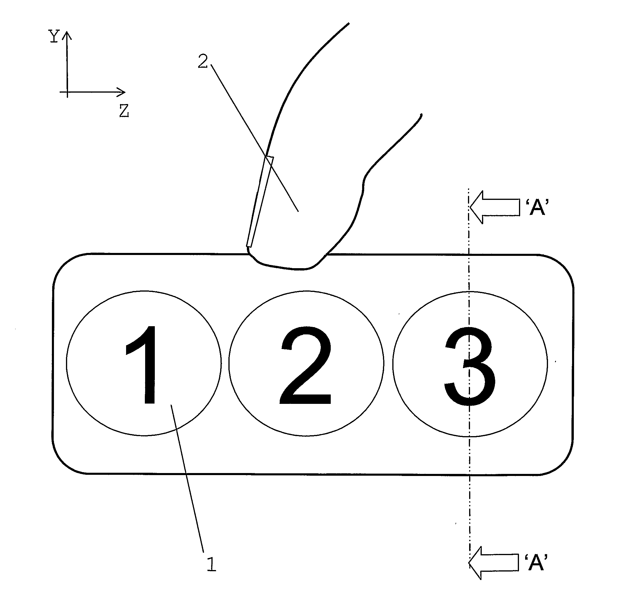
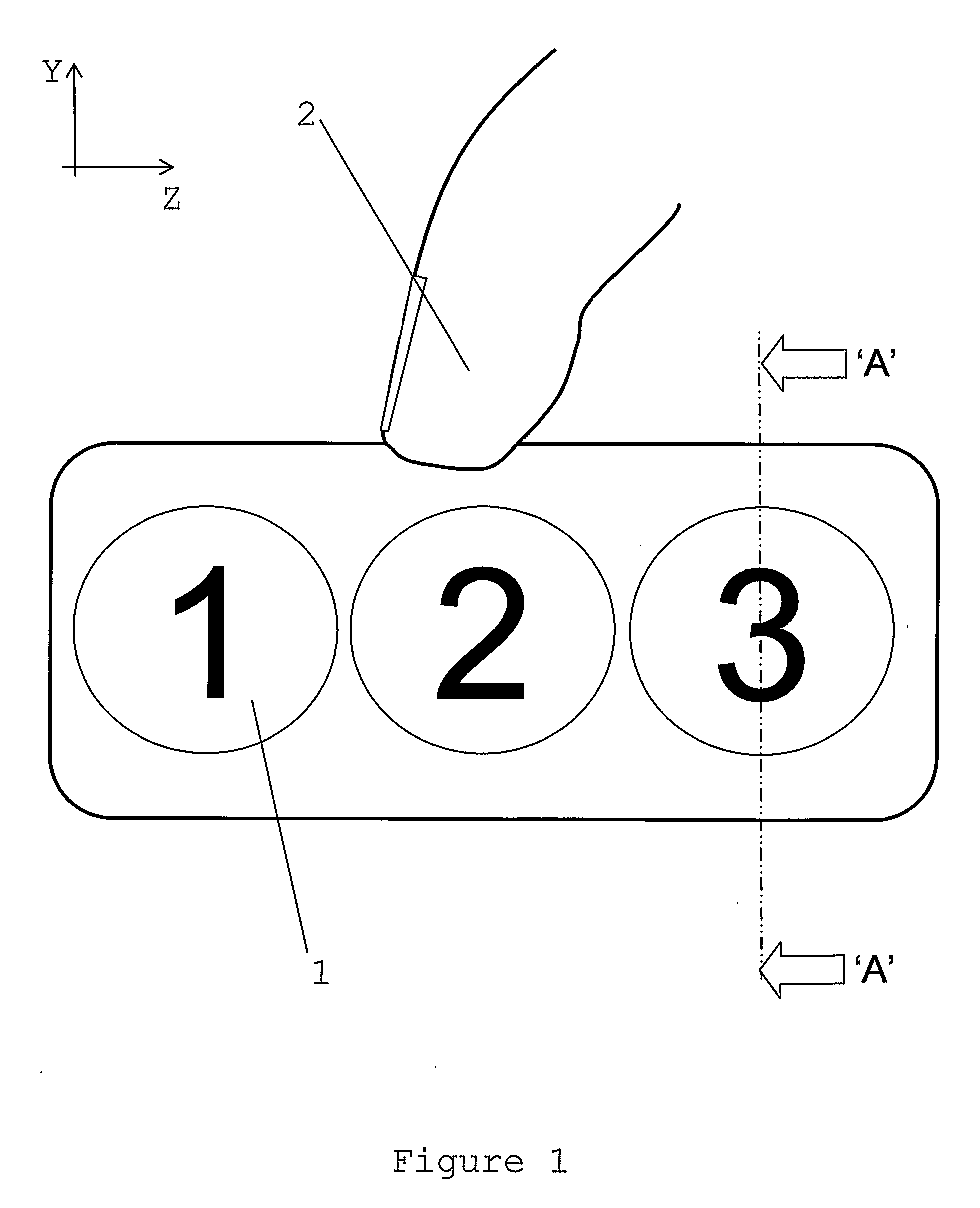
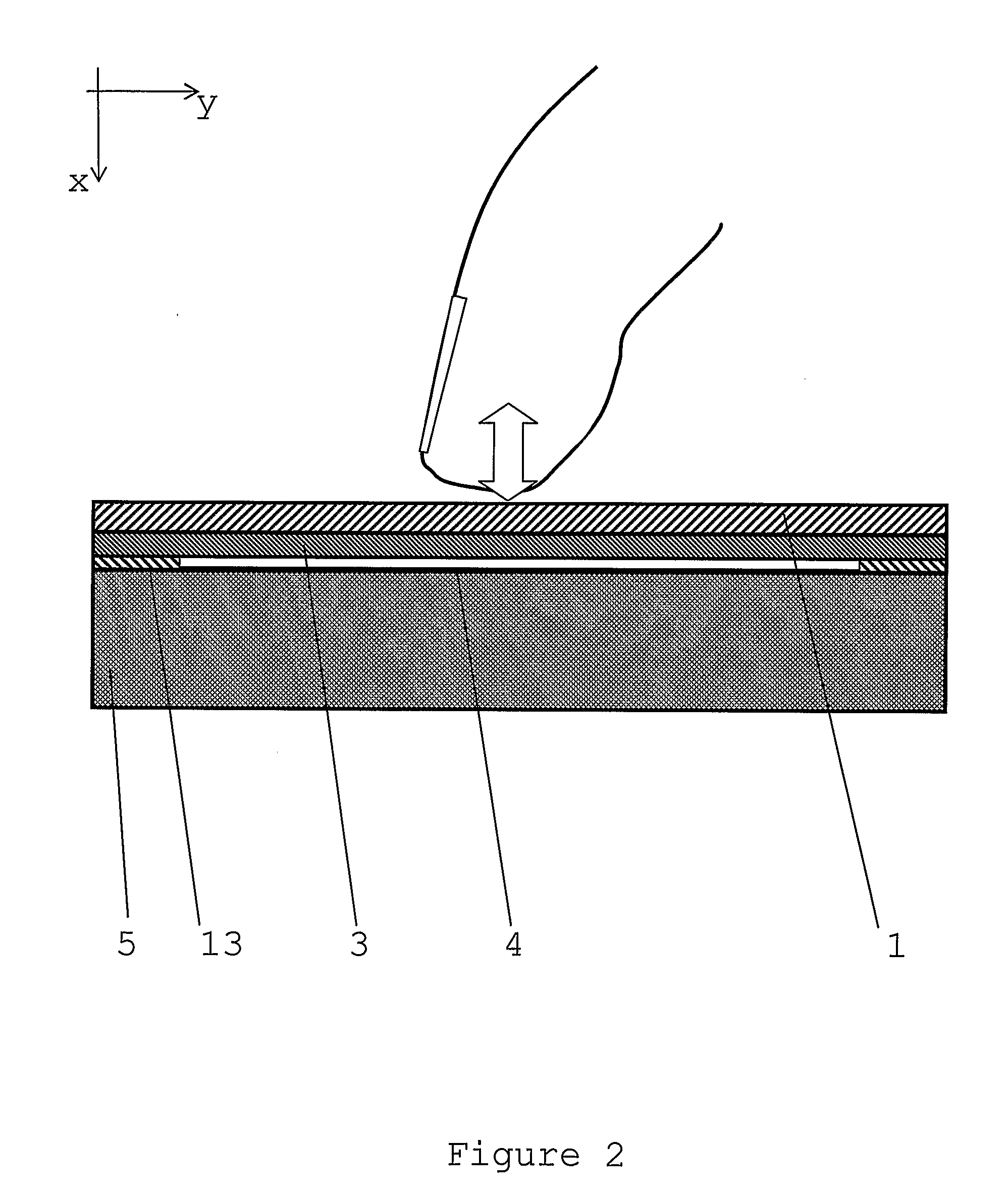
[0035]FIG. 1 shows a plan view of a device according to the invention, in the form of a user interface comprising a push button keypad. A substantially impermeable, robust, protective fascia panel 1 made from stainless steel is printed (or etched) with user graphics. The panel 1 protects the keypad's interior from the environment for reasons of safety, hygiene and reliability. A user presses on the panel 1 with his finger 2. The panel 1 deforms elastically by a small amount when pushed by the user and returns to its original state afterwards. The detector is located behind the push button but is not shown for clarity. The panel 1 can be made from a range of materials which are preferably durable and strong but with some elastic properties. Examples of preferred materials are steel, Acrylonitrile Butadiene Styrene (ABS) mouldings, copper, aluminium, wood, glass fibre, printed circuit board PCB substrates etc. Advantageously, conductive materials also shield against electromagnetic em...

second embodiment

[0044]FIG. 7 shows detectors arranged in an annulus according to the invention in the form of an extended touch detector where the user might apply force at a point along a straight line, curved line or circle. Such annular arrangements have been used in portable music players. Maximum deformation occurs where the user applies force along the circle. The deformation may extend over several detectors. Comparison of the readings from each of the detectors can be used to calculate the position of the applied force. In such constructions it is advantageous to break a continuous target 3 into several individual targets 3 to provide greater differentiation between neighbouring detectors.

[0045]An alternative embodiment of the invention is a joystick. A joystick is attached to the panel 1 so that the user's interaction with the joystick (including upward motion) causes deformation of the panel. The interaction can be sensed by comparing the readings from multiple detectors arranged at vario...


PUM


Abstract

An apparatus for user interfaces is described to measure inductively the deformation of a body (1) comprising at least two laminar conductive elements (3, 4), at least one of which is an AC energized inductor (4), wherein deformation causes relative axial movement between the at least two laminar elements (3, 4) and the maximum deformation distance is limited to prevent damage.

Description

FIELD OF THE INVENTION[0001]This invention relates to a pressure sensitive detector and, in particular to such a detector for use in user interfaces.REVIEW OF THE ART KNOWN TO THE APPLICANT[0002]Push buttons typically detect a user's input by making or breaking electrical contacts. Such buttons are unreliable in harsh environments where foreign matter, fluid or impact can cause electrical contacts to fail. Protective gaiters or seals are notoriously unreliable.[0003]Various alternatives to push buttons are known, including capacitive, infrared and piezo sensors. All are problematic. Capacitive detectors suffer from temperature or humidity drift and are often unable to differentiate between a user's finger and a water droplet, for example. Infra-red touch sensors are expensive and need a transparent panel such as glass between the sensor and the user. Piezo sensors need expensive materials and precision assembly.[0004]Inductive displacement detectors, such as that described by the pr...

Claims


Application Information

Patent Timeline
Patent Type & Authority Applications(United States)
IPC IPC(8): G06F3/041
CPCG06F3/046H03K2217/96038H03K17/97
Inventor KREIT, DARRANHOWARD, MARK ANTHONY
Owner MICROCHIP TECH INC
Why Eureka
Try Eureka