Skylight With Improved Low Angle Light Capture

a low angle light capture and skylight technology, applied in skylights/domes, building roofs, building repairs, etc., can solve the problems of large heat loss in winter and heat gain in summer, insufficient roof support, and inability to provide sufficient roof suppor

Inactive Publication Date: 2014-01-30
REPLEX MIRROR
View PDF10 Cites 8 Cited by
  • Summary
  • Abstract
  • Description
  • Claims
  • Application Information

AI Technical Summary

Problems solved by technology

Unfortunately, skylights also have some inherent, undesirable characteristics that require that choices and compromises be made between the desirable and the undesirable characteristics.
For example, the larger a designer makes the cross-sectional area of the sunlight transmitting path into the room, the more sunlight that is captured and transmitted into the room but also the larger becomes the heat loss in winter and heat gain in summer.
Similarly, the larger the skylight, the more difficult it becomes to provide sufficient roof support for the skylight and avoid water and air leaks.
The tubular skylights provide an alternative with a considerably smaller footprint area to minimize those problems but, because of the relatively small area of their upper opening, their light capture is limited.

Method used


Image

  • Skylight With Improved Low Angle Light Capture
  • Skylight With Improved Low Angle Light Capture
  • Skylight With Improved Low Angle Light Capture

Examples


Embodiment Construction

[0034]U.S. Provisional Application No. 61 / 676,453 filed Jul. 27, 2012, the above claimed priority application, is incorporated in this application by reference.

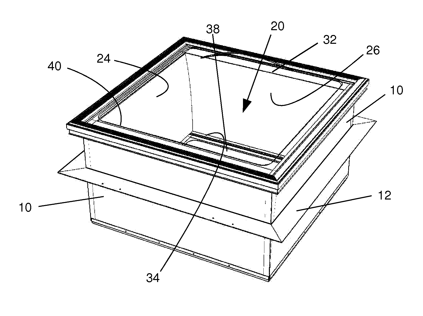
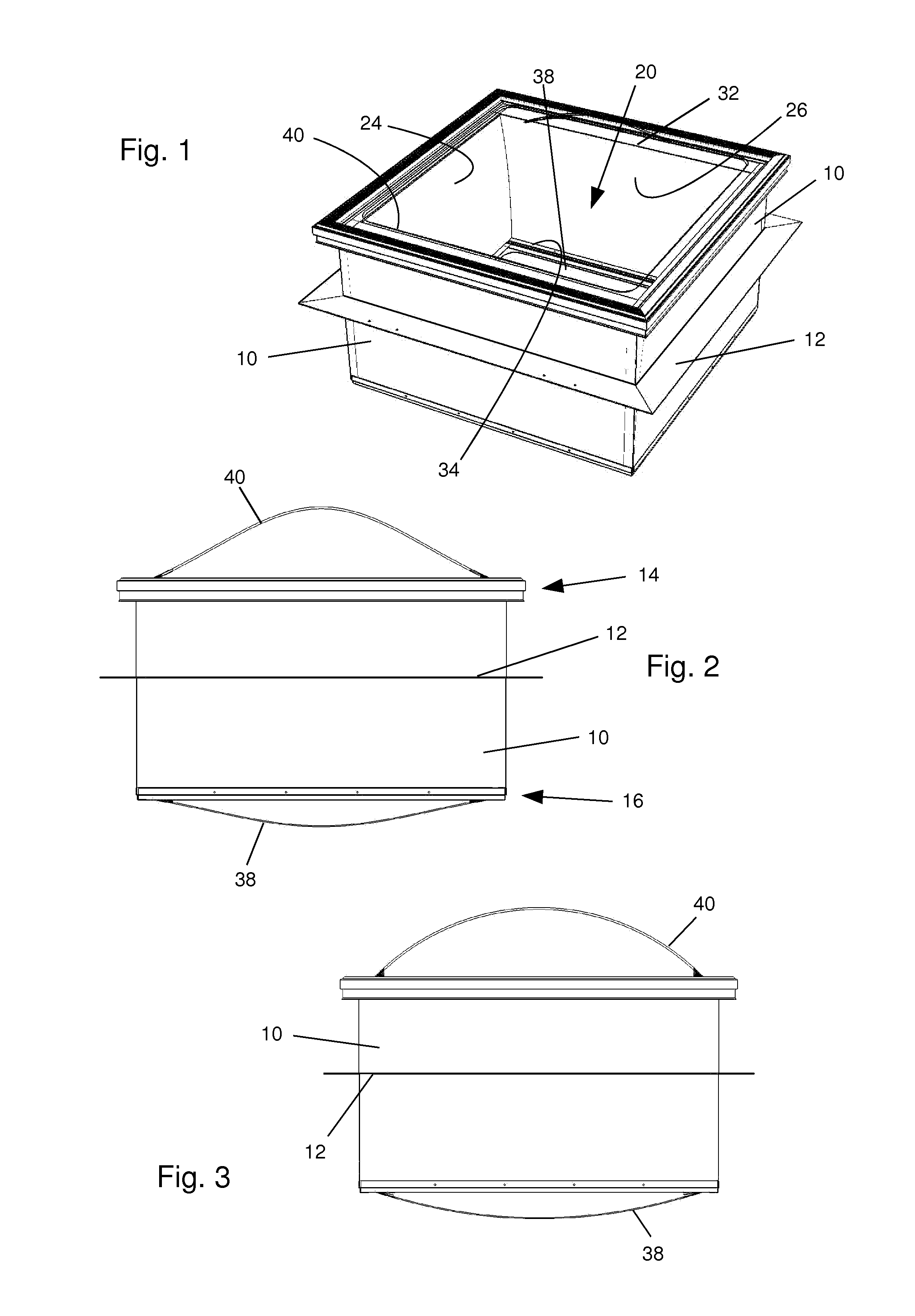
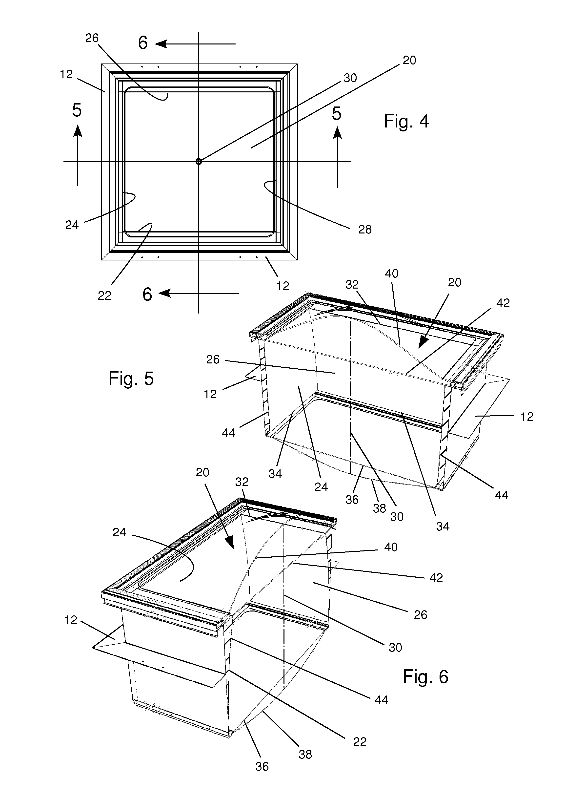
[0035]As will be seen from the following description, the main feature of a skylight constructed according to the invention is that it uses mirror reflective surfaces at the boundaries of the skylight's light transmission passage that have a contour and orientation which reduce the number of reflections of incoming solar rays within the light transmission passage before the rays exit the skylight into the room. Because every reflection results in a portion of the incident light being absorbed by the reflective surface and a portion being reflected, reducing the number of reflections reduces the total absorption of light and consequently increases the sunlight capture efficiency. With skylights that embody the present invention, the increase in sunlight capture efficiency is especially effective for a low altitude sun, such as...


PUM


Abstract

A skylight with a light transmission passage bounded by reflective surface. Centrally facing, curved mirror reflective surfaces are positioned on opposite sides of the passage. The curved reflective surfaces have a curvature slope that becomes progressively greater, with respect to a plane that is perpendicular to the axis, as the surfaces progress from the upper end to the lower end of the passage. The curved mirror surfaces are also curved inward at their upper end. Preferably, the curved mirror surfaces are parabolic and most preferably are formed as a compound parabolic concentrator that is mounted in an inverted orientation. The skylight of the invention also has reflective surfaces that are orthogonal to these reflective surfaces. The orthogonal reflective surfaces can alternatively be either formed with the same curvature and orientation or can be planar.

Description

CROSS-REFERENCES TO RELATED APPLICATIONS[0001]This application claims the benefit of U.S. Provisional Application No. 61 / 676,453 filed Jul. 27, 2012. The above claimed provisional priority application, is hereby incorporated in this application by reference.STATEMENT REGARDING FEDERALLY-SPONSORED RESEARCH AND DEVELOPMENT[0002](Not Applicable)REFERENCE TO AN APPENDIX[0003](Not Applicable)BACKGROUND OF THE INVENTION[0004]This invention relates generally to devices for efficiently transmitting light and more particularly relates to skylights for transmitting light from the sun through a roof to a room below the roof for assisting in illuminating the room with natural sunlight and for doing so in a manner that (1) maximizes the capture efficiency, which is the proportion of the light incident upon the skylight that is transmitted into the room, (2) transmits the sunlight into the room as pleasingly diffuse light and (3) protects the inhabitants of the room from UV light.[0005]For centur...

Claims


Application Information

Patent Timeline
Patent Type & Authority Applications(United States)
IPC IPC(8): E04D13/03
CPCE04D13/033E04D2013/0345
Inventor SCHUETZ, MARK A.SHELL, KARA A.
Owner REPLEX MIRROR
Why Eureka
Try Eureka