
Stationary scanner apparatus with image scanner

Active Publication Date: 2014-01-30
NEC PLATFORMS LTD
View PDF0 Cites 6 Cited by
  • Summary
  • Abstract
  • Description
  • Claims
  • Application Information

AI Technical Summary

Benefits of technology

The present invention is a stationary scanner apparatus that can simplify the structure and reduce the size of the apparatus. It allows for efficient use of space around the apparatus. The image scanner is supported so that it can rotate about a horizontal axis, making it possible to move the readable area of the scanner in a vertical direction without the need for a lifting mechanism. This results in a reduction of cost and complexity. The image scanner itself does not move in the vertical direction, which allows for space below the scanner. The apparatus can be held at any position using a frictional force between inclination holders and guide members. Overall, the technical effects of the present invention are simplification, size reduction, space utilization, and cost reduction.

Problems solved by technology

Thus, the structure of the scanner is complicated and is large in size.
Accordingly, such a bar code scanner becomes costly.
Therefore, it is difficult to use the movement space for placing a basket or the like, for example.
Thus, such a bar code scanner also has a problem in effective use of spaces around the scanner.

Method used


Image

  • Stationary scanner apparatus with image scanner
  • Stationary scanner apparatus with image scanner
  • Stationary scanner apparatus with image scanner

Examples


Embodiment Construction

[0022]An embodiment of a stationary scanner apparatus according to the present invention will be described below with reference to FIGS. 1 to 7.

[0023]A stationary scanner apparatus 10 according to an embodiment of the present invention is used for an item registration operation in a POS system in which a store clerk conducts an item registration operation of registering items to be purchased by customers while another store clerk conducts a checkout operation.

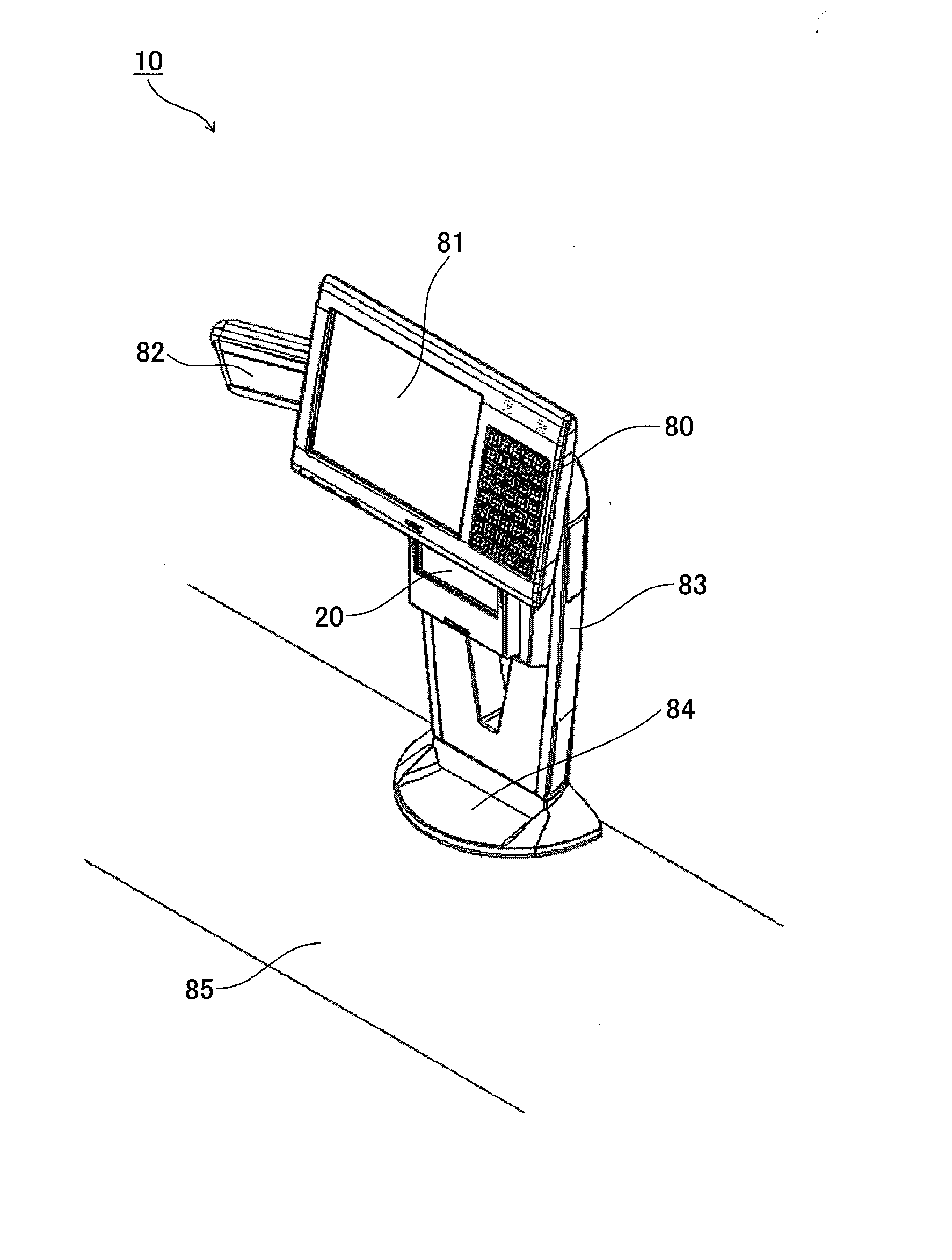
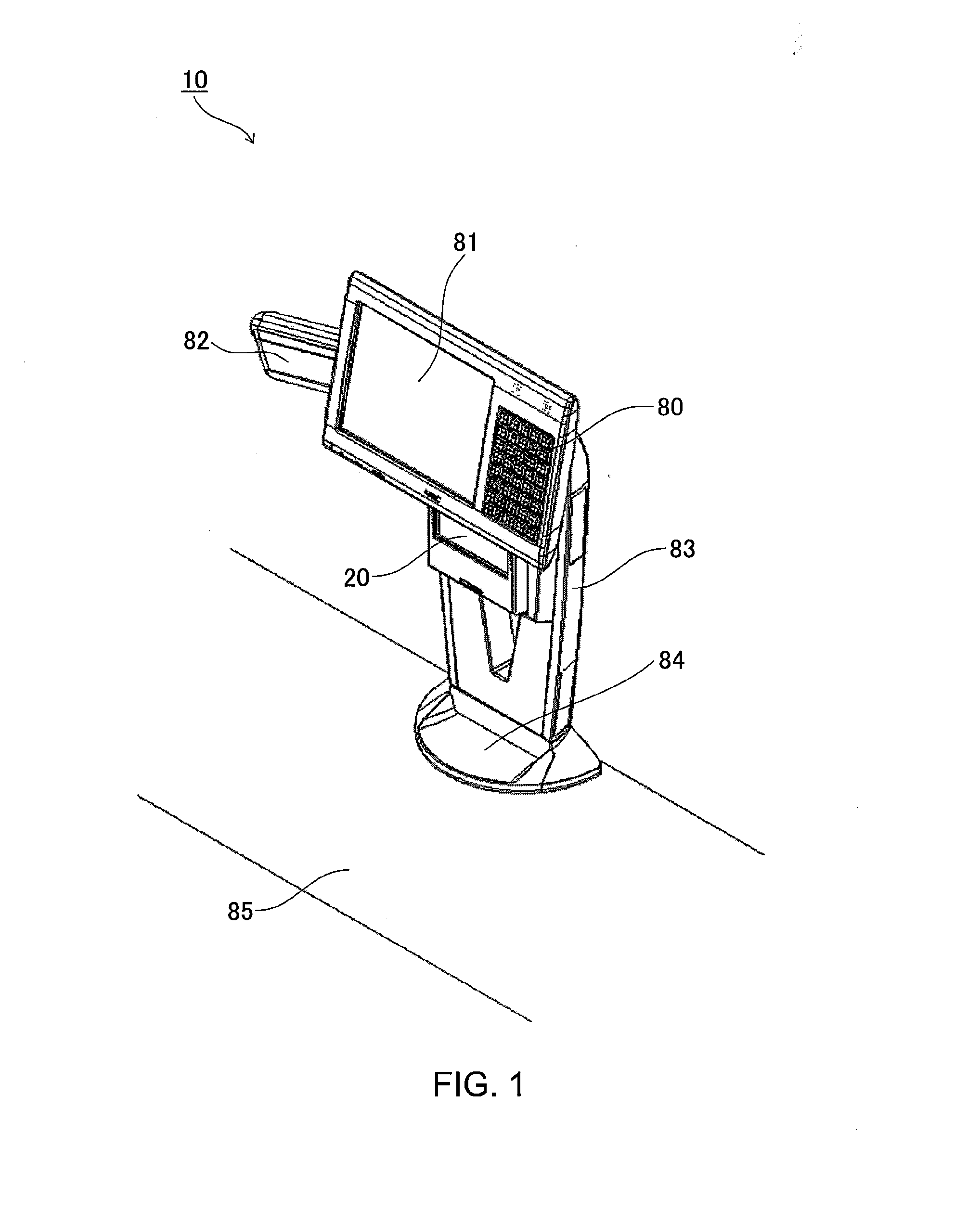
[0024]As shown in FIG. 1, the stationary scanner apparatus 10 has an image scanner 20 such as a CCD image sensor capable of reading an item code assigned to an item, a keyboard 80 that receives various inputs, a store clerk display 81 with a touch panel, a customer display 82, a support member (support portion) 83 for supporting those components, and a towel reception portion 84 for receiving a towel therein. The reference numeral 85 of FIG. 1 represents a bagger stand (mount stand) on which the stationary scanner apparatus 10 ...


PUM


Abstract

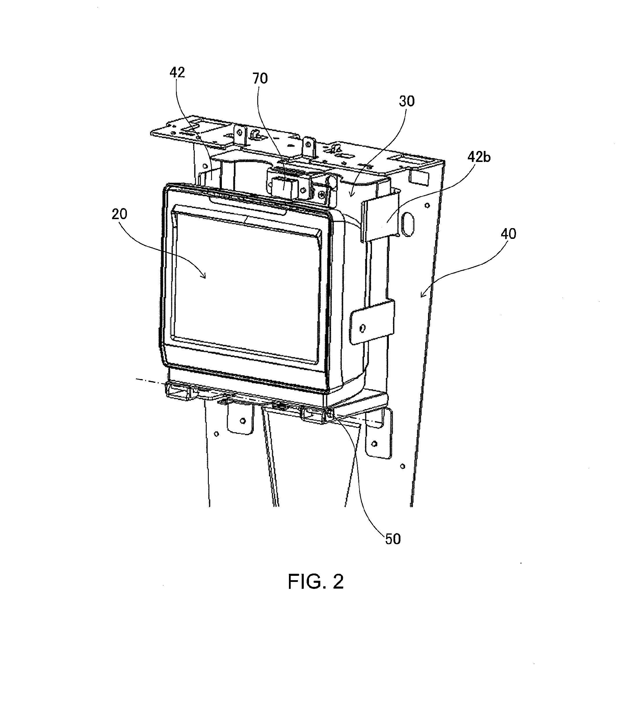
A stationary scanner apparatus 10 comprises an image scanner 20 operable to read an item code, an imager attachment member 30 fixed to the image scanner 20, a support frame 40 configured to support the imager attachment member 30 in a state in which the image scanner 20 and imager attachment member 30 are rotatable about a horizontal axis with respect to the support frame 40, and a support portion 83 fixed to the support frame 40. The imager attachment member 30 has a first plate-shaped inclination holder 32a formed on one side of lateral sides of the imager attachment member 30 and a second plate-shaped inclination holder 32b formed on another side of the lateral sides of the imager attachment member 30. The support frame 40 has a first plate-shaped guide member 42a arranged in contact with the first inclination holder 32a and a second plate-shaped guide member 42b arranged in contact with the second inclination holder 32b. A rotational position of the image scanner 20 is held with a frictional force produced between the inclination holders 32a, 32b and the guide members 42a, 42b.

Description

[0001]This application is based upon and claims the benefit of priority from Japanese patent application No. 2012-165407, filed on Jul. 26, 2012, the disclosure of which is incorporated herein in its entirety by reference.BACKGROUND[0002]1. Field of the Invention[0003]The present invention relates to a stationary scanner apparatus with an image scanner, and more particularly to a stationary scanner apparatus with an image scanner having a readable area that is movable in a vertical direction.[0004]2. Description of the Related Art[0005]Generally, in a point-of-sales (POS) system, a store clerk conducts an item registration operation of registering items to be purchased by customers, and another store clerk conducts a checkout operation. A stationary scanner apparatus is used for an item registration operation. Some stationary scanner apparatuses use what is called an image scanner, which reads a bar code of an item with an imager such as a charge-coupled device (CCD) image sensor.[0...

Claims


Application Information

Patent Timeline
IPC IPC(8): H04N1/10
CPCH04N1/10G07G1/0018
Inventor MIKAMI, HAYATO
Owner NEC PLATFORMS LTD
Learn More