Communication system, communication apparatus and radio resource allocating method
- Summary
- Abstract
- Description
- Claims
- Application Information
AI Technical Summary
Benefits of technology
Problems solved by technology
Method used
Image
Examples
embodiment 1
[0050]FIG. 7 is a block diagram showing a configuration of communication apparatus 100 according to Embodiment 1 of the invention.
[0051]Communication apparatus 100 primarily includes antenna 101, radio communication section 102, MAC section (MAC layer) 110, RLC section (RLC layer) 120, and packet data convergence protocol (PDCP) section (PDCP layer) 130. Communication apparatus 100 is, for example, a communication terminal apparatus, such as a mobile apparatus.
[0052]Antenna 101 receives a signal and outputs the signal to radio communication section 102. Antenna 101 transmits the signal received from radio communication section 102.
[0053]Radio communication section 102 converts the signal received from antenna 101 from a radio signal to a baseband signal, demodulates the signal, and outputs the resultant signal to MAC section 110. Radio communication section 102 modulates a transmission signal including a retransmission request received from MAC section 110, performs frequency conver...
embodiment 2
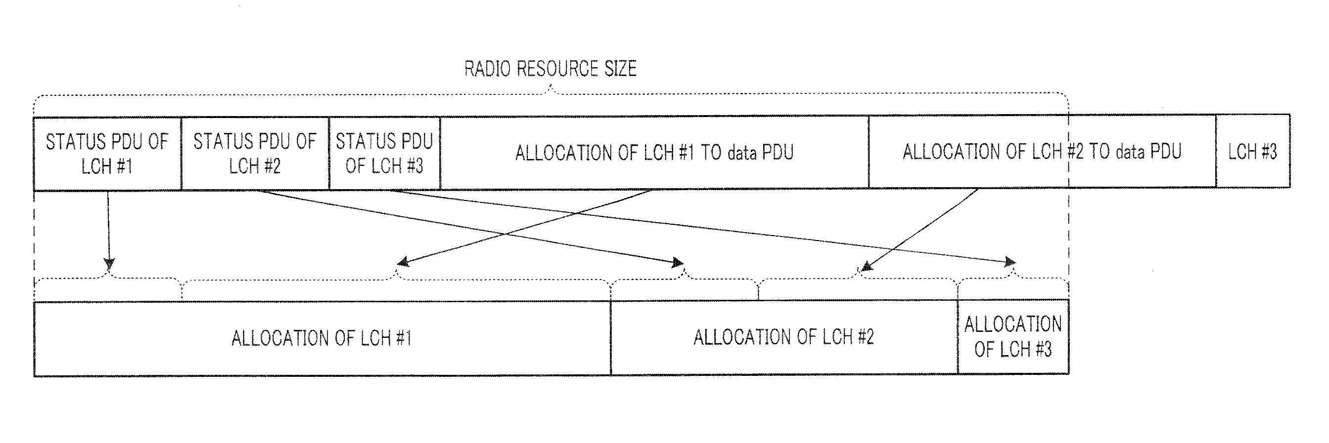
[0092]In the radio resource allocating method of Embodiment 1, the RLC STATUS PDU configuration processing and the RLC data PDU configuration processing may be executed separately and alone.
[0093]Embodiment 2 relates to processing when the RLC STATUS PDU configuration processing is executed alone.
[0094]The basic configuration and operation of a communication apparatus according to Embodiment 2 of the invention are the same as those in Embodiment 1.
[0095]FIG. 10 is a flowchart showing processing in an RLC section (RLC layer) of the communication apparatus to which a radio resource allocating method according to Embodiment 2 of the invention is applied. The steps in which the same processing as that in the flow of FIG. 9 is performed are represented by the same reference numerals.
[0096]In Step S11, RLC section (RLC layer) 120 receives information of a total radio resource size along with an allocated resource size of each LCH from MAC section (MAC layer) 110.
[0097]An RLC STATUS PDU is...
embodiment 3
[0103]Embodiment 3 relates to processing when the RLC data PDU configuration processing is executed alone.
[0104]The basic configuration and operation of a communication apparatus according to Embodiment 3 of the invention are the same as those in Embodiment 1.
[0105]FIG. 11 is a flowchart showing processing in an RLC section (RLC layer) of a communication apparatus to which a radio resource allocating method according to Embodiment 3 of the invention is applied. The steps in which the same processing as the flow of FIGS. 9 and 10 are represented by the same reference numerals.
[0106]In Step S11, RLC section (RLC layer) 120 receives information of a total radio resource size along with an allocated resource size of each LCH from MAC section (MAC layer) 110.
[0107]At a loop end S5, the flow is executed for each LCH in a descending order of priority.
[0108]In Steps S6 to S9, RLC section 120 configures an RLC data PDU. Specifically, in Step S6, RLC section 120 determines whether or not an R...
PUM
 Abstract
Description
Claims
Application Information
 - R&D
- Intellectual Property
- Life Sciences
- Materials
- Tech Scout
- Unparalleled Data Quality
- Higher Quality Content
- 60% Fewer Hallucinations
Browse by: Latest US Patents, China's latest patents, Technical Efficacy Thesaurus, Application Domain, Technology Topic, Popular Technical Reports.
© 2025 PatSnap. All rights reserved.Legal|Privacy policy|Modern Slavery Act Transparency Statement|Sitemap|About US| Contact US: help@patsnap.com


