Method of provisioning h-vpls services in a multi-domain mpls network

a multi-domain, mpls technology, applied in the direction of digital transmission, data switching by path configuration, electrical equipment, etc., can solve the problems of increasing complexity and extremely multi-dimensional tasks of tasks

Active Publication Date: 2014-02-06
ECE TELECOM LTD
View PDF7 Cites 5 Cited by
  • Summary
  • Abstract
  • Description
  • Claims
  • Application Information

AI Technical Summary

Benefits of technology

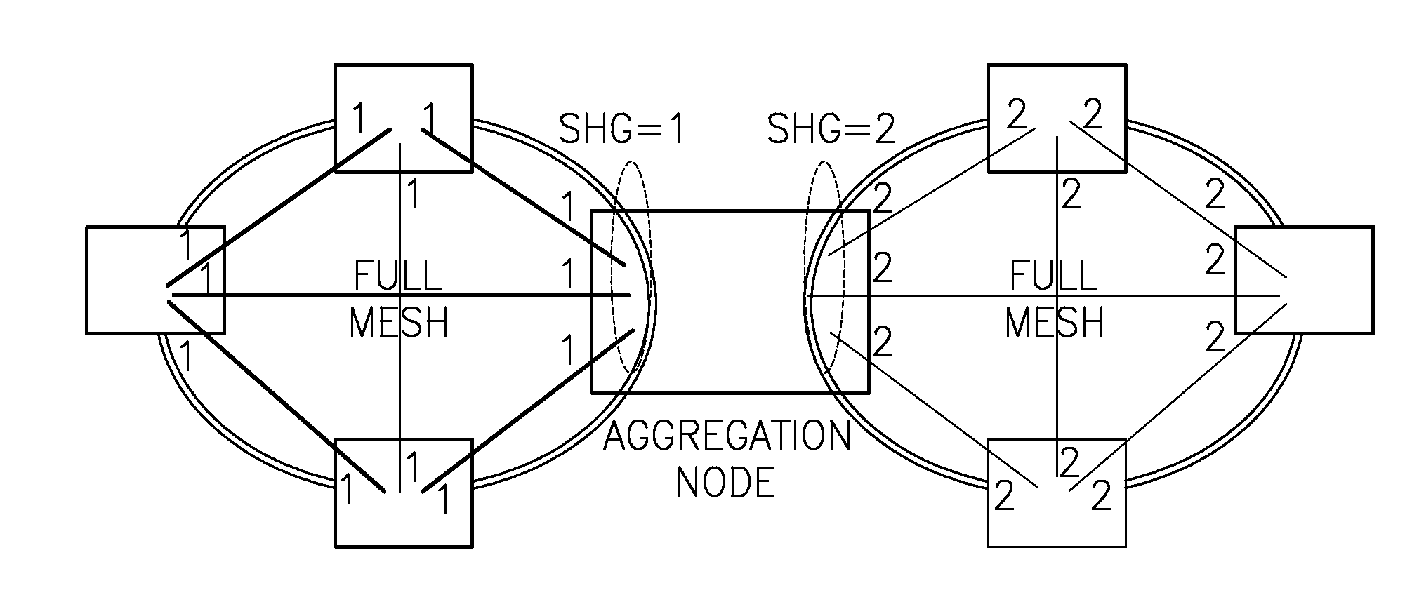
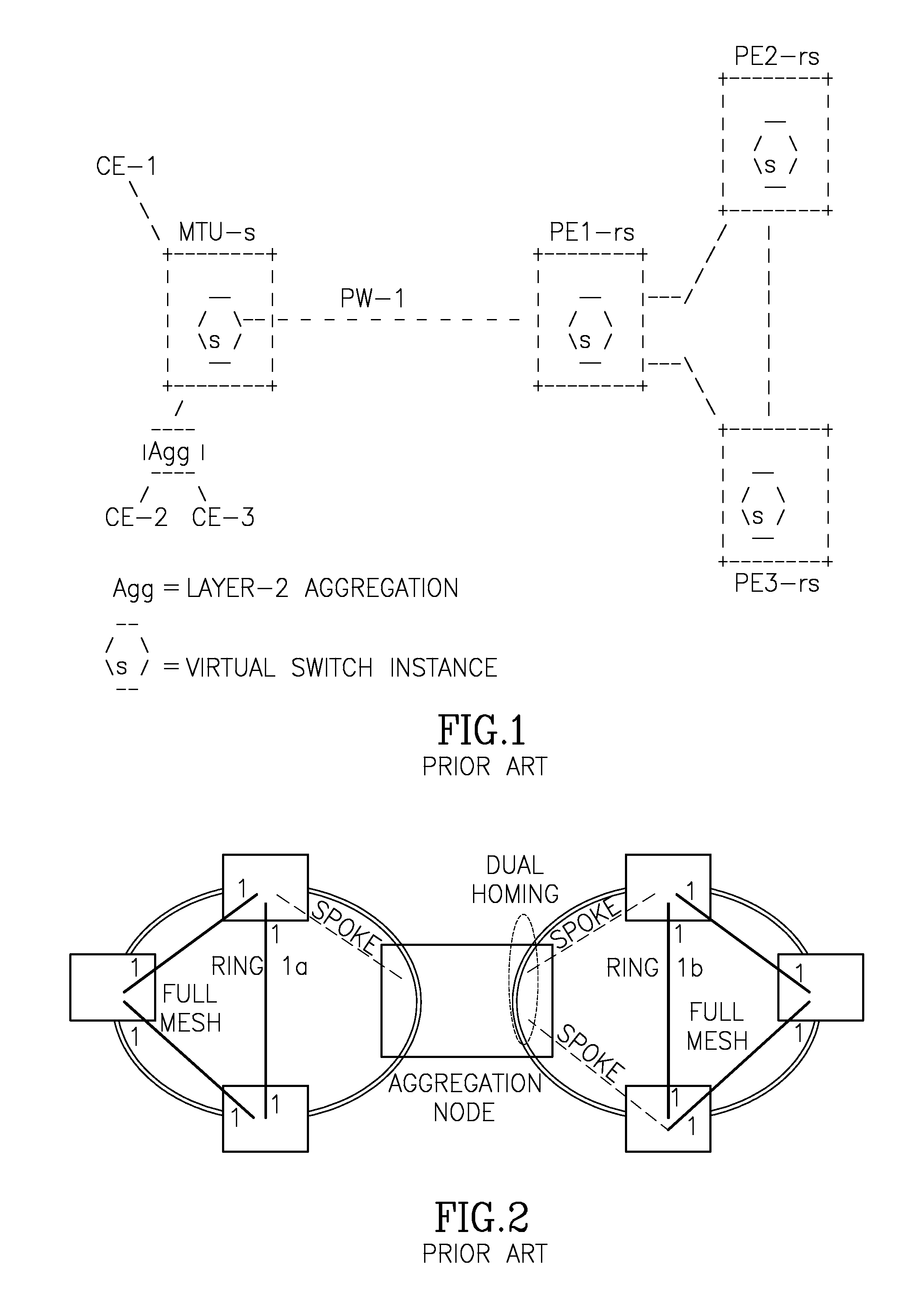
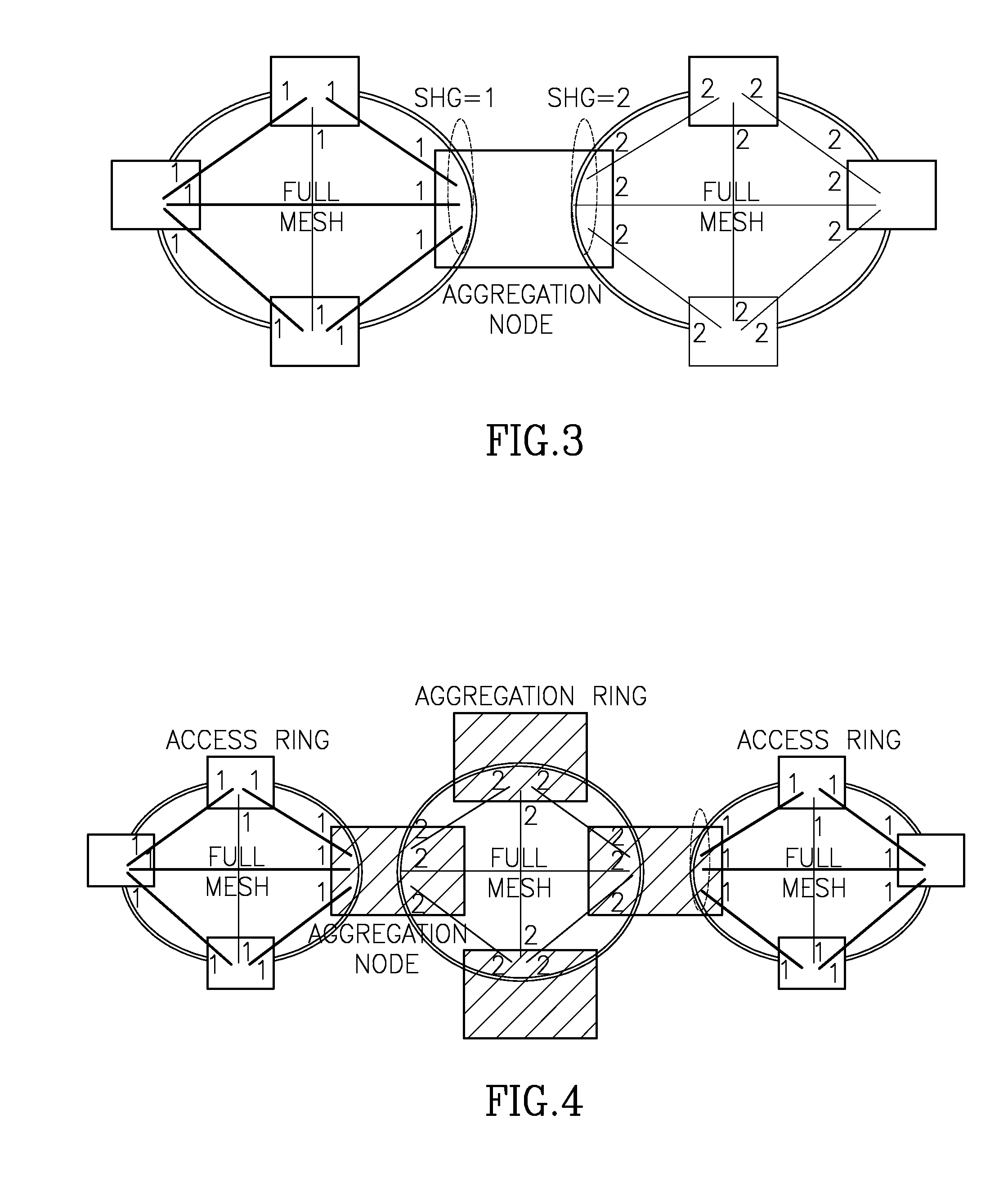
[0028]It is an object of the present invention to provide a method for forming multiple SHG groups in a multi-domain MPLS network, in order to allow any specific H-VPLS traffic to cross / cover the network without generating traffic loops.
[0042](iv) transmitting H-VPLS traffic of the MPTMP service via two or more VPLS domains in the MPLS network, wherein service traffic received along a first PW is prevented from being conveyed along a second PW associated with a PW indication that is identical to the PW indication (e.g. identical to the SHG-N) associated with the first PW.
[0060]causing prevention of conveyance of service traffic received along a first PW from being conveyed along a second PW associated with a PW indication that is identical to the PW indication associated with the first PW, when H-VPLS traffic of the MPTMP service will be transmitted via two or more VPLS domains in the MPLS network.
[0065](d) enabling transmission of H-VPLS traffic of the MPTMP service via two or more VPLS domains in the MPLS network, wherein service traffic received along a first PW is prevented from being conveyed along a second PW associated with a PW indication that is identical to the PW indication associated with the first PW.

Problems solved by technology

As will be appreciated by those skilled in the art, each network node in a typical network usually handles not one, but multiple traffic services (H-VPLS), so that the task becomes extremely multidimensional task and the complexity thereof increases dramatically.

Method used


Image

  • Method of provisioning h-vpls services in a multi-domain mpls network
  • Method of provisioning h-vpls services in a multi-domain mpls network
  • Method of provisioning h-vpls services in a multi-domain mpls network

Examples


Embodiment Construction

[0073]In this disclosure, the term “comprising” is intended to have an open-ended meaning so that when a first element is stated as comprising a second element, the first element may also include one or more other elements that are not necessarily identified or described herein, or recited in the claims.

[0074]In the following description, for the purposes of explanation, numerous specific details are set forth in order to provide a thorough understanding of the present invention. It will be apparent, however, that the present invention may be practiced without these specific details.

[0075]FIG. 7 provides a schematic representation of an MPLS network that comprises domains D1, D2, D3 and a spoke domain D0.

[0076]Let us assume that an H-VPLS path is to be established over the exemplified network, for the provisioning of a certain service. This path is schematically shown by arrows. Traffic arrives via node X, passes through domains D1, D2, D3 and D0 and reaches terminal T along a spoke...


PUM


Abstract

A method is disclosed for provisioning loop free H-VPLS traffic service in a multi-domain MPLS network having interconnected domains. The method comprises: provisioning pseudo wires (PWs) for MPTMP services in each domain of the MPLS network; defining multiple Split Horizon Groups (SHGs) in the network, wherein each SHG corresponds to a domain, for the H-VPLS service traffic and for each specific node of the MPLS network, automatically assigning indications to SHG and the pseudo wires connected to the specific node, wherein the same indication is assigned to all pseudo wires belonging to the same group (SHG-N), and wherein the step of assigning is characterized in that when traffic belonging to H-VPLS service crosses a border network node located between two interconnected domains, the SHG-N indication of PWs remains the same within a VPLS domain thereby preventing the service traffic from returning to the domain of origin.

Description

CROSS-REFERENCE TO RELATED APPLICATIONS[0001]This application claims priority of Israel Patent Application No. 221303, filed Aug. 5, 2012, the disclosure of which is incorporated by reference herein in its entirety.FIELD OF TECHNOLOGY[0002]The present invention relates to provisioning of MPLS-based H-VPLS services in a network comprising multiple H-VPLS domains.BACKGROUNDLegend[0003]MPLS network—multi protocol label switching network;[0004]LSP or tunnel—a label-switched path (LSP) is a path extending through an MPLS network. The path is set up based on criteria in the forwarding equivalence class (FEC). The path begins at a label edge router (LER), which makes a decision on which label to prefix to a packet based on the appropriate FEC. It then forwards the packet along to the next router in the path, which swaps the packet's outer label for another label, and forwards it to the next router. The last router in the path removes the label from the packet and forwards the packet based ...

Claims


Application Information

Patent Timeline
Patent Type & Authority Applications(United States)
IPC IPC(8): H04L12/723H04L45/50
CPCH04L45/50H04L45/68H04L12/4633
Inventor AGMON, GIDEONDUKHOVNY, VADIM
Owner ECE TELECOM LTD
Why Eureka
Try Eureka