
Camera stabilization apparatus and method of use

a technology for stabilizing equipment and cameras, applied in the direction of instruments, camera body details, stands/trestles, etc., can solve the problems of inherently unstable devices, heavy weight of most camera stabilization devices, and inability to work well

Inactive Publication Date: 2014-02-06
CARNEY PETER L
View PDF9 Cites 47 Cited by
  • Summary
  • Abstract
  • Description
  • Claims
  • Application Information

AI Technical Summary

Benefits of technology

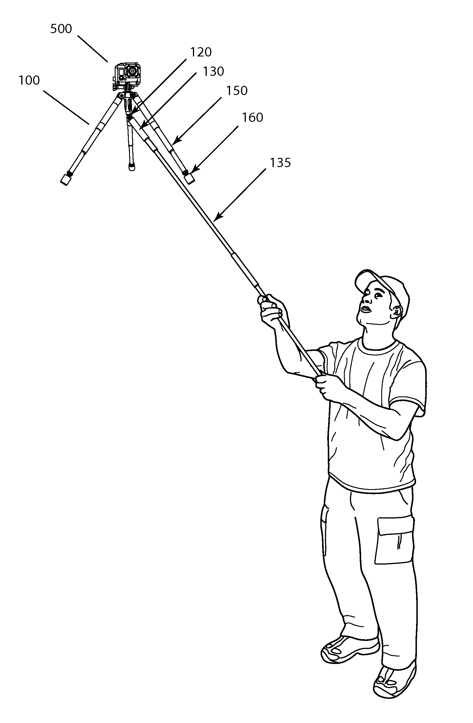
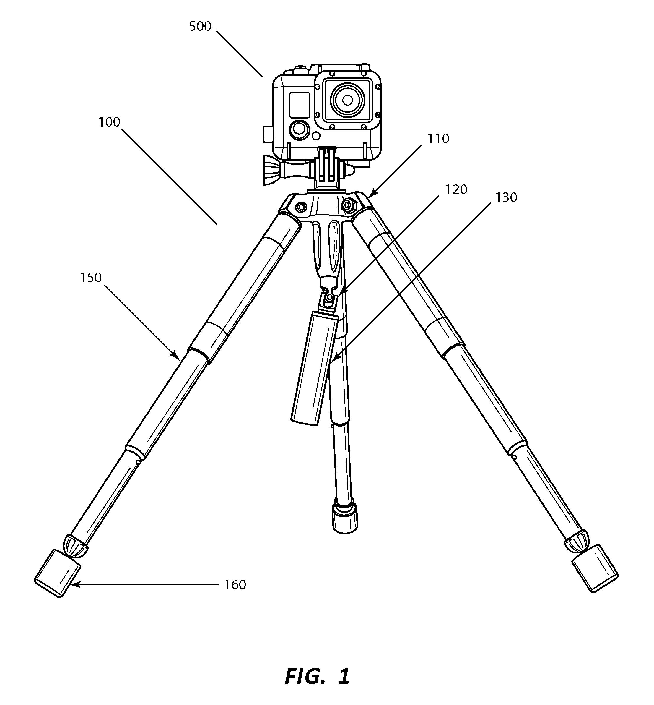
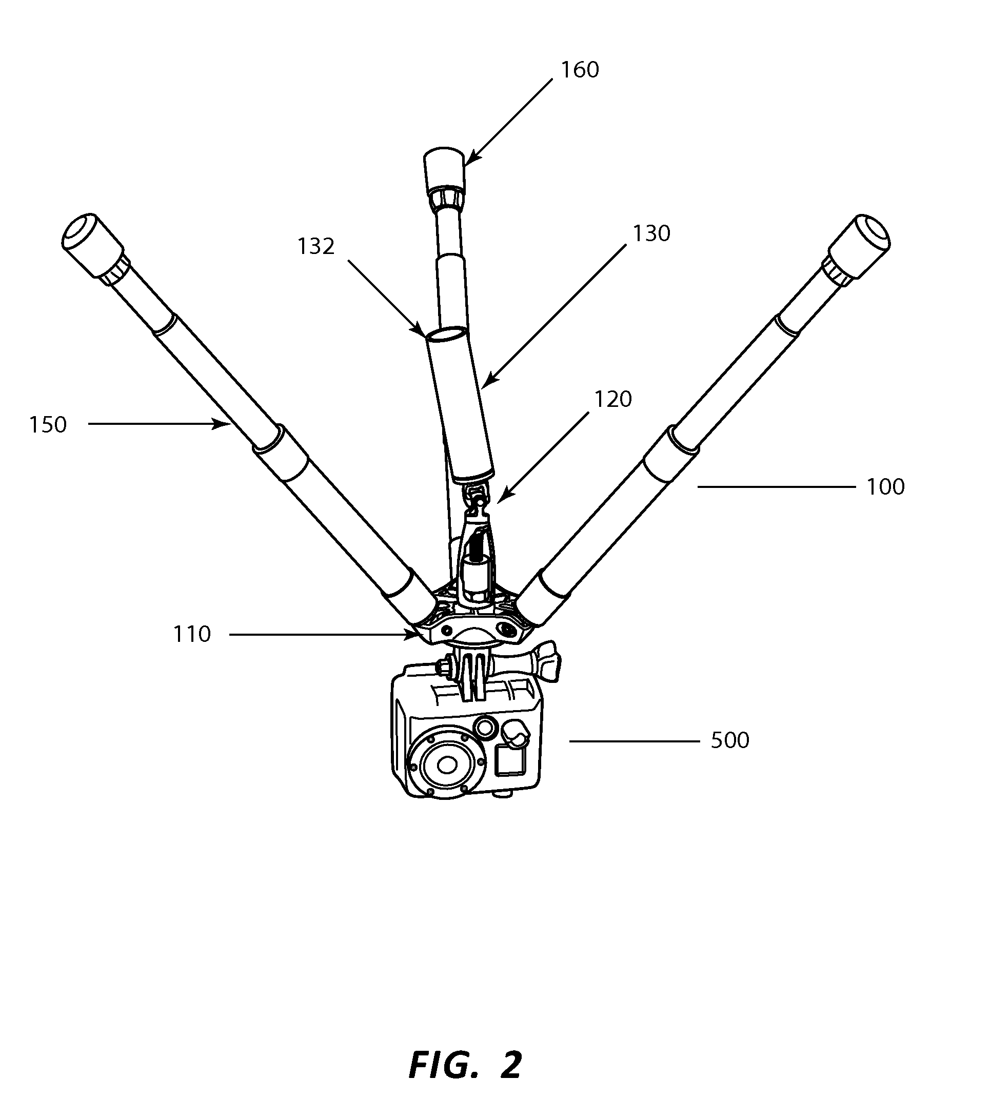
This patent is about a camera stabilization device that allows a camera to be flown out of arms reach of the operator while still maintaining orientation towards the subject matter. The device includes a camera mount with a plurality of counter-balance support legs, a three-axis rotatable bearing, and a handle for panning and sharp rotational movements. The counter-balance support legs can be telescoping and attached to a jib pole assembly or a microphone boom pole. By adjusting the moment of inertia and changing the position of the counter-balance support legs, the device can be easily adjusted for different camera orientations. Overall, the device allows for smoother and more stable filming while in the air.

Problems solved by technology

However, these types of devices do not work well when it is necessary to have the camera in motion along with the subject and, this is especially true, when the camera is hand held or supported by a user.
Due to the requirement of a high moment of inertia, most camera stabilization devices are heavy and can be unwieldy.
However, these devices are inherently unstable and require the operator to employ both hands to control field of view and stability.
A limitation for each of these devices is that they cannot be extended away for the user or operator.
However, this device does not include any form of stabilization and if combined with any of the other aforementioned devices, the user would not be able to reach up and control at least one axis of the camera in order to direct the shot or completely stabilize the image.
Another limitation of the above mentioned devices is that the stabilization device, with the camera, must maintain a single configuration or orientation, such as camera always on top of the stabilization counter-balance assembly or having the camera suspended below the stabilization assembly.
However, when the camera is mounted above the stabilization assembly, the stabilization assembly will interfere with filming at or near ground level.

Method used


Image

  • Camera stabilization apparatus and method of use
  • Camera stabilization apparatus and method of use
  • Camera stabilization apparatus and method of use

Examples


Embodiment Construction

[0033]For the purposes of promoting an understanding of the principles in accordance with the disclosure, reference will be made to the embodiments illustrated in the drawings and specific language will be used to describe the same. It will nevertheless be understood that no limitation of the scope of the disclosure is thereby intended. Any alterations and further modifications of the inventive features illustrated herein, and any additional applications of the principles of the disclosure as illustrated herein, which would normally occur to one skilled in the relevant art and having possession of this disclosure, are to be considered within the scope of the disclosure.

[0034]As used in this specification and the appended claims, the singular forms “a,”“an,” and “the” include plural referents unless the context clearly dictates otherwise. In describing and claiming the present disclosure, the following terminology will be used in accordance with definitions set out below. The term ca...


PUM


Abstract

The present invention is a dynamically balanced, light weight multifunctional, camera stabilization device that allows a film or digital video camera to be flown out of arms reach of the operator while still maintaining orientation toward the subject matter and can easily be configured to allow the camera to be oriented, above or below, the stabilization assembly.

Description

[0001]This application claims priority to U.S. provisional patent application 61 / 679,070, filed Aug. 3, 2012 and is related to U.S. patent application 13 / 517,846, filed Jun. 14, 2012. The disclosures therein incorporated by reference.BACKGROUND OF THE INVENTION[0002]A number of devices have been introduced to help film makers produce clear, stabile motion picture, home movies or video images, including, tripods, monopods, clamps, booms, etc. These devices work well when the camera is in a relatively fixed position and the subjects are in motion. However, these types of devices do not work well when it is necessary to have the camera in motion along with the subject and, this is especially true, when the camera is hand held or supported by a user.[0003]There are some devices designed to stabilize a camera when it is hand held or supported by the user that are based on the principle of lowering the center of gravity of the assembly below a three-axis pivot point where the user's handl...

Claims


Application Information

Patent Timeline
Patent Type & Authority Applications(United States)
IPC IPC(8): G03B17/56
CPCG03B17/561F16M11/10F16M11/28F16M11/32F16M13/04
Inventor CARNEY, PETER L.
Owner CARNEY PETER L
Learn More