
Self-actuating bleed valve for gas turbine engine

a gas turbine engine and self-actuation technology, which is applied in the direction of machines/engines, mechanical equipment, transportation and packaging, etc., can solve the problems of difficult driving of compressors, difficulty in driving compressors, and difficulty in fully providing power in the turbine section of the gas turbine engine, so as to eliminate all the complicated controls and be less expensive

Inactive Publication Date: 2007-10-11
RAYTHEON TECH CORP
View PDF11 Cites 36 Cited by
  • Summary
  • Abstract
  • Description
  • Claims
  • Application Information

AI Technical Summary

Benefits of technology

[0005] In a disclosed embodiment of this invention, a gas turbine engine compressor section is provided with a self-actuated bleed valve. Pressure is applied to two surfaces of a valve poppet, and the pressure within the compressor chamber itself is utilized to drive the valve poppet. At lower pressure conditions, such as found at start-up, the valve will move to an open position. A spring may assist in this positioning. As the compressor pressure increases, the valve poppet will move to a closed position and will remain at this closed position during most operational conditions. The present invention, by providing a valve actuated by the very working fluid, eliminates all of the complicated controls, etc. of the prior art powered valves. Thus, the present invention is less expensive and much simpler than the prior art.
[0007] In a disclosed embodiment of this invention, the self-actuated valve includes a valve poppet with a first certain area piston surface, and a second, opposed, smaller piston area. The second piston surface faces into a pressurized chamber communicating with the compressor section. The first piston surface faces an enclosed chamber. A hollowed rod guides the poppet movement and communicates pressurized air into the enclosed chamber. Since the chamber is closed, the enclosed chamber will solely see a static pressure. At lower pressure conditions, a total pressure applied on the second piston surface, plus a spring force, will overcome the force on the larger first piston surface in the enclosed chamber.
[0008] However, as the overall pressure within the pressurized chamber increases, the static pressure in the enclosed chamber will also increase, and eventually the force from the increasing pressure on the larger piston surface will become sufficiently high that it drives the valve poppet to the closed position. In this manner, the valve poppet is open at start-up and driven to be closed after the pressure has built up sufficiently from the compressor. When the valve is open, air from the compressor section is dumped, thus lowering the load to drive the compressor during start-up conditions.

Problems solved by technology

At start-up, the turbine section of the gas turbine engine has not begun to fully provide power.
Thus, driving the compressor, as an example, is more challenging than it will be at steady state conditions.
The powered valves are somewhat expensive and complex.

Method used


Image

  • Self-actuating bleed valve for gas turbine engine
  • Self-actuating bleed valve for gas turbine engine
  • Self-actuating bleed valve for gas turbine engine

Examples


Embodiment Construction

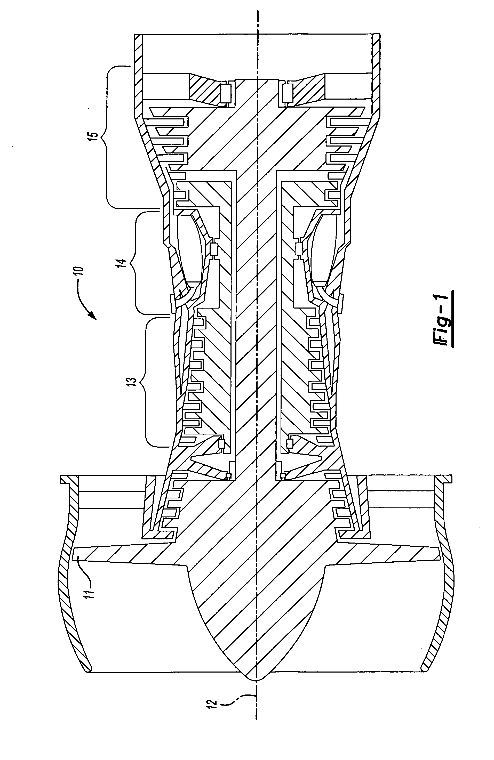
[0014]FIG. 1 shows a gas turbine engine 10. As known, a fan section 11 moves air and rotates about an axial center line 12. A compressor section 13, a combustion section 14, and a turbine section 15 are also centered on the axial center line 12. FIG. 1 is a highly schematic view, however, it does show the main components of the gas turbine engine. Further, while a particular type of gas turbine engine is illustrated in this figure, it should be understood that the present invention extends to other types of gas turbine engines.

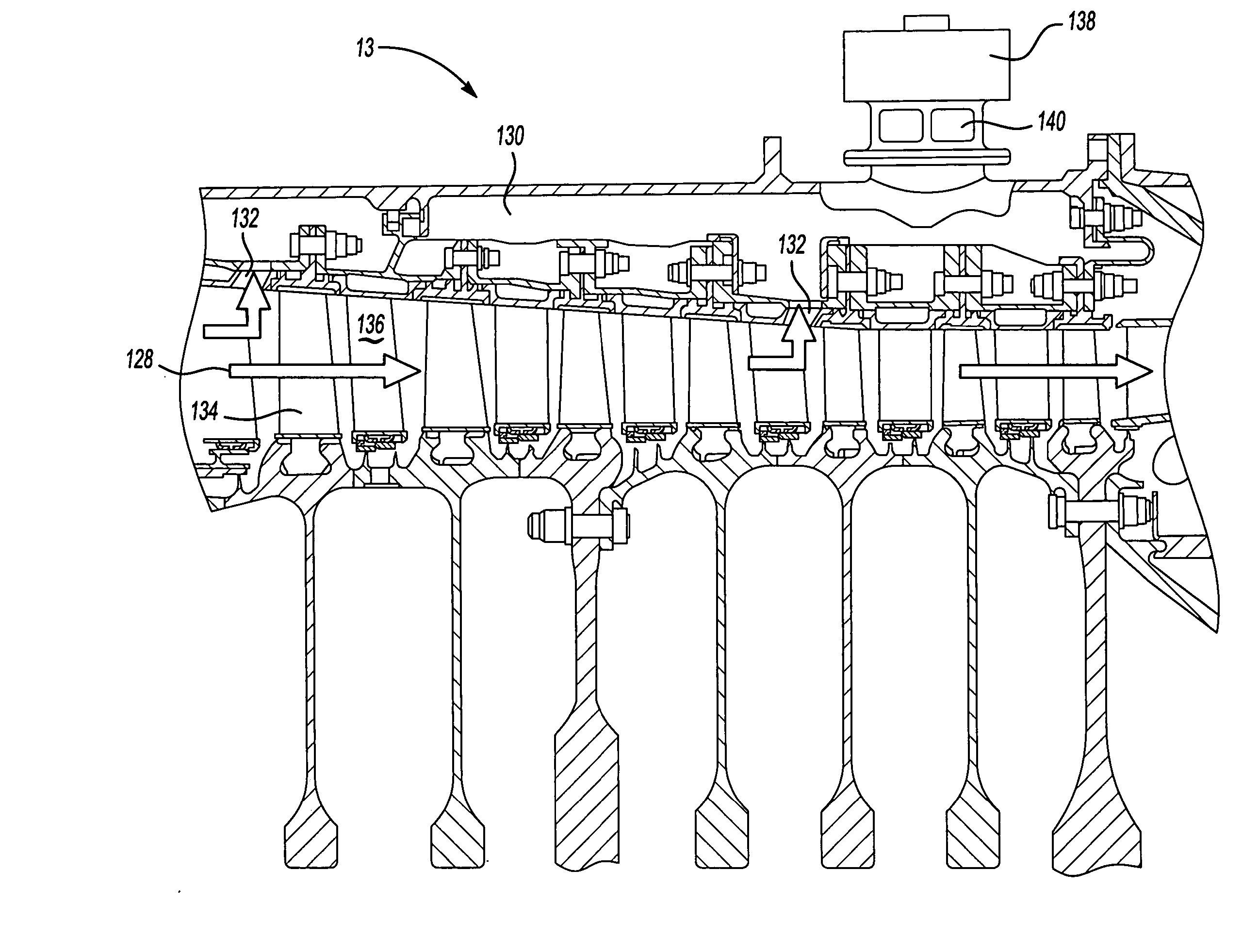
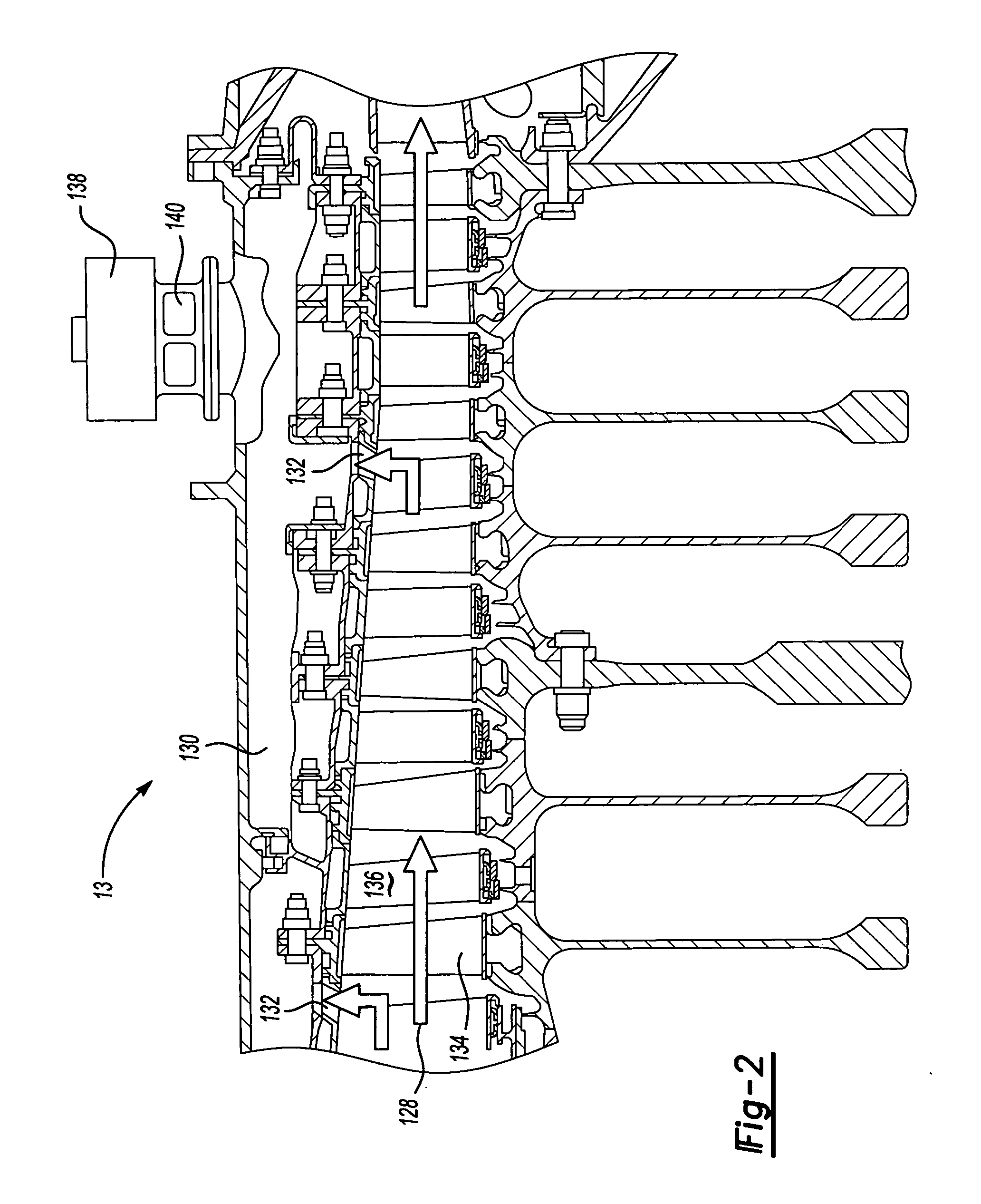
[0015]FIG. 2 shows the compressor section 13 having a plurality of rotating compressor blades 134 and fixed vanes 136 in a compressor gas path. A secondary air plenum 130 is positioned outwardly of the compressor blades. Compressed air flows through openings 132 into chamber 130. As shown, a compressed gas flow path 128 passes along the compressor section, and downstream into the gas turbine engine as shown more generally in FIG. 1. A bleed valve 138 has open...


PUM


Abstract

A bleed valve for bleeding air from a compressed air chamber at start-up of a gas turbine engine is self-actuated. The bleed valve moves between open and closed positions based on the pressure within a compressed air chamber. In this manner, the bleed valve is driven to an open position at low pressure conditions and to a closed position once the pressure within the compressor chamber becomes higher and closer to operating pressures. In this manner, a relatively inexpensive and simple bleed valve can be utilized to provide the start-up bleed valve function.

Description

BACKGROUND OF THE INVENTION [0001] This application relates to a self-actuated bleed valve for assisting start-up of a gas turbine engine. [0002] Gas turbine engines are provided with a number of functional sections, including a fan section, a compressor section, a combustion section, and a turbine section. Air and fuel are combusted in the combustion section. The products of the combustion move downstream, and pass over a series of turbine rotors, driving the rotors to provide power. The turbines drive the compressor and fan rotors. [0003] At start-up, the turbine section of the gas turbine engine has not begun to fully provide power. Thus, driving the compressor, as an example, is more challenging than it will be at steady state conditions. It is known in prior art gas turbine engines to include a bleed valve to bleed air away from the compressor section during start-up and reduce the load to drive the compressor. Known bleed valves utilize some form of electric, pneumatic or hydr...

Claims


Application Information

Patent Timeline
Patent Type & Authority Applications(United States)
IPC IPC(8): F02C6/08
CPCF02C6/08F02C9/52F02C9/18F04D27/0215F04D27/023
Inventor BORCEA, ALEXANDRU
Owner RAYTHEON TECH CORP
Learn More