Engine

Active Publication Date: 2014-02-13
YAMAHA MOTOR CO LTD
View PDF5 Cites 7 Cited by
  • Summary
  • Abstract
  • Description
  • Claims
  • Application Information

AI Technical Summary

Benefits of technology

[0008]In the engine according to the first preferred embodiment of the present invention, the exhaust pipe is cooled by lubricating oil of the engine body whose temperature is lower than the temperature of the engine body as the lubricating oil flows in the oil jacket of the exhaust pipe. This prevents melting of the exhaust pipe because the exhaust pipe is cooled.

Problems solved by technology

If the temperature of an exhaust pipe becomes too low this may impact the operation or performance of the engine.
Therefore, when the temperature of the seawater is low, the wall temperature of the exhaust pipe stays at an excessively low temperature.
If the exhaust pipe stays at an excessively low temperature, condensation forms inside the exhaust pipe because water vapor in the exhausted g

Method used


Image

  • Engine
  • Engine
  • Engine

Examples


Example

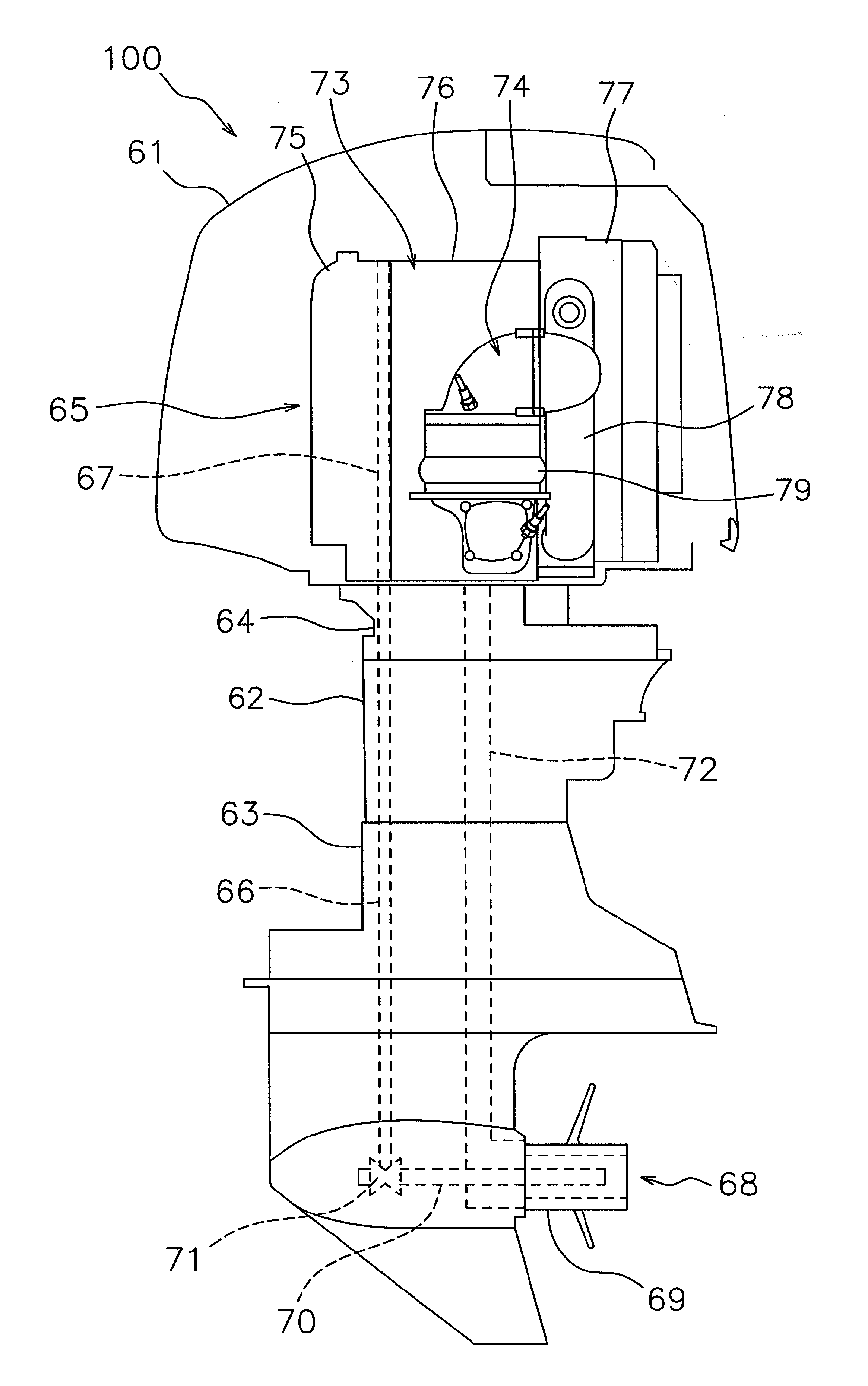
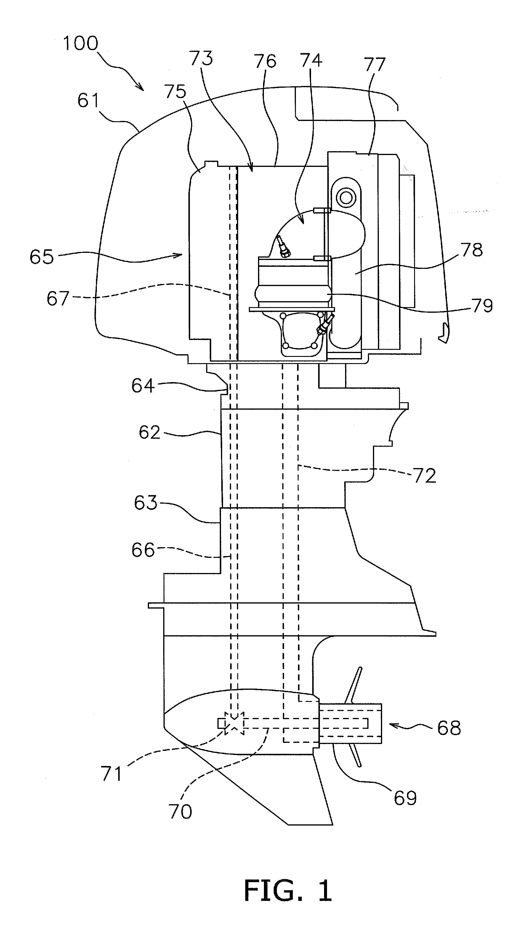
[0020]An engine according to a first preferred embodiment of the present invention will now be described with reference to the drawings. FIG. 1 is a side view showing an outboard motor 100 mounted with an engine 65 according to the first preferred embodiment of the present invention. As shown in FIG. 1, the outboard motor 100 includes an engine cover 61, an upper casing 62, a lower casing 63, an exhaust guide portion 64, and the engine 65. To facilitate ease of understanding, in FIG. 1 the engine cover 61 is shown in a cross-sectional view.

[0021]The engine 65 is disposed inside the engine cover 61. As shown in FIG. 1, a drive shaft 66 is disposed within the upper casing 62 and the lower casing 63. The drive shaft 66 is disposed along the upward and downward direction within the upper casing 62 and the lower casing 63. The drive shaft 66 is linked to a crankshaft 67 of the engine 65. A propeller 68 is disposed at the lower portion of the lower casing 63. The propeller 68 is arranged ...


PUM


Abstract

An engine includes an engine body and an exhaust pipe. The engine body includes a combustion chamber and an oil passage in which lubricating oil flows. The exhaust pipe includes an exhaust passage and an oil jacket. The exhaust passage is linked to the combustion chamber. The oil jacket is linked to the oil passage.

Description

BACKGROUND OF THE INVENTION[0001]1. Field of the Invention[0002]The present invention relates to an engine.[0003]2. Description of the Related Art[0004]The exhaust gas from an internal combustion engine can readily cause an exhaust pipe to heat to a high temperature. For this reason, a mechanism for cooling the exhaust pipe using cooling water is used. The outboard motor disclosed in Japanese Patent Laid-open No. 09-309497, for example, provides an engine and a heat exchanger. The engine includes a cooling water jacket for cooling the engine. The heat exchanger cools the heated cooling water circulating in the cooling water jacket. In this way, the starting performance of the engine can be improved more by cooling the engine indirectly than by cooling the engine directly. The heat exchanger cools the cooling water in the cooling water jacket by exchanging heat between the cooling water in the cooling water jacket and seawater from a periphery of the marine vessel. After the seawater...

Claims


Application Information

Patent Timeline
IPC IPC(8): F01N3/04
CPCF01N3/046F01M5/001F01N3/2046F01N2560/025F01N2560/14F01N2560/20F01N2590/021F01N2590/022F01P3/202F01P2003/006Y02T10/12
Inventor NAKAYAMA, KOICHIKINOMOTO, NAOKI
Owner YAMAHA MOTOR CO LTD
Why Eureka
Try Eureka